Many of you are probably familiar with spot temperature guns, those infrared (IR) test tools where you point a laser beam at an object (e.g., motor, pump, fluorescent light ballast, air conditioning or heating duct, or your barbecued steak). Point, shoot and voila! You have a temperature on the LCD display.
Nowadays, it is likely that you have done the same thing with an infrared camera, also known as a thermal imager. Not only does the infrared camera give you a temperature number, it also gives you an often fascinating image of what appears to be happening with your object of interest. Technology is great, huh? It’s certainly easier, and safer, than putting your hand on something or using a contact temperature thermocouple.
But have you ever looked at the screen of a spot IR tool or an infrared camera and scratched your head saying:
"That just cannot be; no way is it that hot or that cold!
I know everything is running fine here.”
Maybe you thought: “This thing just isn’t working right.
Maybe the batteries are low.”

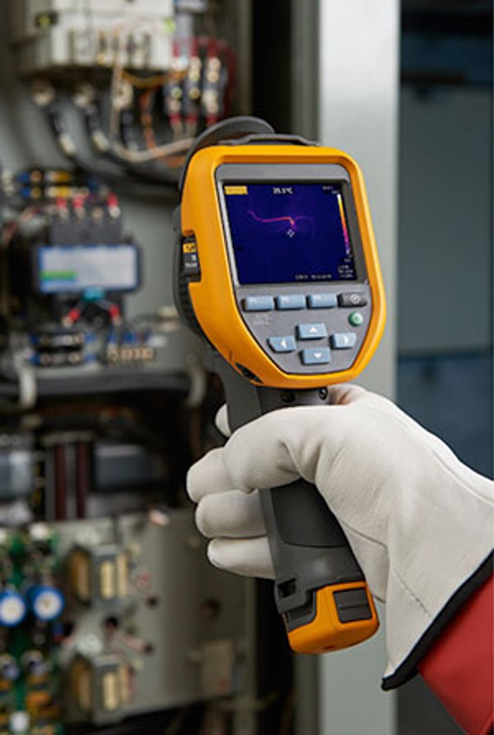
Figure 1: An infrared camera can provide useful information about apparent hot and cold spots in electrical cabinets, but results can be misread unless you understand how different materials emit heat
What IR Cameras Measure
Spot IR guns and infrared cameras don’t actually “measure” temperature. (You might be raising your eyebrows right about now, thinking: “The number is right there on the screen.”) But guess what? Those infrared tools don’t really “measure” temperature!
However, all is not lost. These tools are still unbelievably useful and often critical for individuals involved in maintenance reliability in facilities and plants.
This article will be a refresher for some, but for others, (those with raised eyebrows, perhaps) it will be a deeper, practical understanding about how IR cameras work. This knowledge should help you make better diagnoses and decisions, and ultimately get the job done with greater confidence and less frustration. While this article will not go into the detailed mathematics and hundreds of years of science behind how it is known what is really going on, it will cover the truth of the situation and tell you what you need to do to deal with it and move on with your work as usual. The only difference is that you will now be armed with practical knowledge. This knowledge will make things go faster and help you get better results.
Think about this: Did you ever notice a pattern relative to the times you thought the temperature value was off for the type of material or surface you were inspecting? Did you notice that shiny objects made of metals or highly polished surfaces seem to have a role in whether your spot IR gun shows strange readings or your infrared camera shows peculiar hot or cold spots that you know could not be correct? Don’t worry, this is completely normal and should be expected with some types of equipment and component surfaces.
Now, back to what IR cameras measure and how that can help answer why those temperatures are likely off.
All About the Heat
Thermal imagers (infrared cameras) and spot temperature tools don’t actually see “temperature.” They see infrared energy, otherwise known to most of us as “heat” energy. This infrared energy is all around us in the universe, in varying amounts. Some things produce heat. Some things absorb heat. Some things reflect heat. Heat is always flowing from where it is in high amounts to areas where there is less heat. This energy is moving.
Infrared cameras, like what most of you have in your plants today, can see heat coming off the surfaces of objects that you are inspecting. Most have passive detectors that work like the human eye, except they see infrared heat energy, whereas the eyes detect visible light energy. Just like human eyes are able to detect different colors of visible light, an infrared camera can detect different amounts and levels of infrared energy, and where it is moving. Are you following so far?
 Figure 2: The electromagnetic spectrum covers many types of energy, including radio waves, X-rays, high energy gamma rays and even visible light; infrared cameras detect wavelengths that are outside the visible spectra and most commonly associated with heat
Why Material and Type of Surface Matters
A thermal imaging camera sees infrared energy coming from all over, such as the piece of equipment you are inspecting, the ceiling, the floor, other equipment, etc. Different surfaces can absorb, give off, and reflect infrared energy in different ways. Some materials can even have some infrared heat energy traveling through them. This is not unlike the energy that makes up visible light. With visible light, some objects reflect all of it or only certain colors. Some objects absorb all visible light. For example, black is actually a lack of color. Other objects, like common glass, allow much of the visible light to pass through.
Let’s apply this same concept to infrared energy, or heat. It is an easy way to think about it and the parallels are very close. Just keep in mind that the same object may treat visible energy and infrared energy differently. You might have to forget what your own eyes are telling you and instead think about what the infrared camera eyes or spot IR eye is telling you.
So what does this all mean? It means that not everything may be as it seems on the infrared camera or spot temperature gun. What these tools are actually doing is taking in the infrared energy, processing the signals created by the sensors and using that information to calculate an apparent temperature, which is then displayed on the LCD screen. With infrared cameras, the brain of the tool also creates a picture of the different amounts of heat and where they are apparently located. Pretty cool, huh?
Remember the Three Variables
Part of the calculation involves variables. The three primary variables, which often have the greatest effect on the math, are known in the infrared world as emissivity, reflected background and transmissivity. From a practical standpoint, emissivity is how reflective or “infrared shiny” a surface is. Reflected background is the infrared energy that is coming from somewhere else, but reflecting off of that infrared shiny surface. Transmissivity is how much of the infrared energy can pass through the material. (This article is not going to discuss much about transmissivity because most of the things inspected in maintenance reliability settings are opaque, so there is little concern about the infrared heat passing straight through a motor or the components of the switchgear. One big exception, however, is the infrared transparent window or IR window, but that is a topic for another time.) Most of the time, the only heat energy that maintenance reliability thermographers really care about is the heat coming from the actual piece of equipment. That is, the heat being given off from that equipment, not the stuff that is reflected from somewhere else or some other piece of equipment.

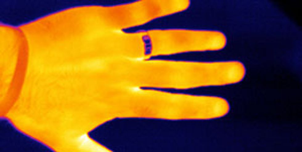
Figure 3: An example of how emissivity can affect an infrared image, as the ring is the same temperature as the hand, but due to a lower emissivity value, the ring does not emit as much infrared towards the camera; it also reflects infrared from cooler areas, so low emissivity and high reflectivity make the ring appear significantly cooler
How the Emissivity Number Works
The emissivity number is measured on a scale of zero to one. A value of zero means the surface is so shiny to infrared that all you will likely ever see is just infrared reflection from somewhere else. (Reflected infrared background is high in this case.) To the contrary, an emissivity of one means an infrared detection tool can see a really great picture of the target’s actual heat and an excellent apparent temperature calculation. In the real world, however, the values are always somewhere in between. Determining what that number actually is for any surface can be a real challenge the lower the number goes. However, most maintenance inspection work is qualitative and comparative in nature, so knowing an exact, precise and truly accurate temperature of an object is not really needed. That’s not to say it cannot be done, but it might end up being a lot of work. As a general rule, try not to knowingly use any temperature calculation on an object with a 0.6 emissivity value or less because the variables become so unmanageable and inconsistent that it is just not worth the added effort for only an incremental increase in confidence. It’s much better to rely on practical tips and tricks to know that you have a reflection and work around it to still get an analysis of what is going on and make a reasonable decision on what is really happening. In general, shiny metallic surfaces have an emissivity value too low to provide accurate or meaningful images.
Table 1 – Emissivity Values for Common Surfaces| Material | Emissivity |
|
Water
|
0.98
|
|
Ice
|
0.97
|
|
Electrical tape, black plastic
|
0.95
|
|
Paint, oil, average
|
0.94
|
|
Paper, black, dull
|
0.94
|
|
Rubber
|
0.93
|
|
Concrete
|
0.92
|
|
Porcelain, glazed
|
0.92
|
|
Tar paper
|
0.92
|
|
Paper, white
|
0.90
|
|
Lacquer, black, shiny
|
0.87
|
|
Shellac, black, shiny
|
0.82
|
|
Cast iron, rough casting
|
0.81
|
|
Iron, oxidized
|
0.74
|
|
Steel, rusty red
|
0.69
|
|
Iron, sheet galvanized, burnished
|
0.23
|
|
Brass, dull, tarnished
|
0.22
|
|
Cast iron, polished
|
0.21
|
|
Steel, sheet, nickel plated
|
0.11
|
|
Aluminum, rough surface
|
0.07
|
|
Copper, commercial burnished
|
0.07
|
From a purely practical standpoint, as long as you realize that something you are looking at with your infrared tool (e.g., camera or spot IR) might be giving off more infrared reflection than what is really coming from the inside, you are a step ahead of the game. Then, knowing whether it really matters for what you need to do or knowing what you can do about it is really what pushes you across the finish line.
Hopefully, your infrared eyes have been opened wide for the first time, or at least seeing a little more clearly than before, and you are able to go out and tackle your inspection work with more confidence. The topic of emissivity, along with many others that surround infrared cameras and spot temperature tools, can go wide and deep. A significant amount of information can be found when, and if, you desire. Don’t be afraid of asking why and questioning what your eyes or your test tools are telling you.
You are the brain behind the tools. Make sure you understand how they work and what limitations they have before and while using them. This is the only way to ensure your expectations for tool performance are level set so you can get the job done day in and day out.
How to Recognize a Questionable or Low Emissivity/Reflectivity Problem?
- Are you looking at something that is shiny or reflective in any way?
- Is the material surface made of a bare metal? (Polished metals are usually low emissivity. Rusted or heavily corroded metals can have a higher emissivity and not have infrared reflections.)
- Are you looking at your object from a really steep angle?
- Is the surface being inspected extremely smooth or mirror-like? (The surface can often produce very distinct reflections in both visible light and infrared.)
- Do you see an unexpected, but apparent hot or cold spot in one of the above situations that does not make sense based on your understanding of how that component or equipment works?
- Have you tried the “thermographer two step?” Move a little to the left and then a little to the right, or a little higher and then a little lower to see if the apparent hot or cold spot moves position as you move.
If you answered “yes” to any of these questions, you may need to be concerned about low emissivity and infrared reflections from other places confusing your infrared image and/or apparent temperature value.
How to Get the Job Done When Low Emissivity Stands in the Way?
- Change the material surface when possible and safe to do so. This can be done by adding a surface with a high emissivity that conducts heat well from whatever you put it on. Examples are electrical tape, paint, a high emissivity decal or sticker, or you can scuff up the material surface. Important Safety Note: Do NOT do this on live electrical systems, live rotating equipment, or things dangerously hot or chemically reactive.
- Inspect instead parts of the object that may be in very close contact with the reflective parts. They will likely be at about the same actual temperature even though the apparent temperature and/or infrared image may be very different. For example, inspect the cable insulation instead of the terminal block or bus bar.
- Don’t inspect at steep angles greater than 30 degrees when possible. Even though a surface might be high emissivity at a normal angle of view, it may become very reflective at steep angles. Think about how the asphalt pavement is not reflective when you look straight down at it, but can reflect the sky and look like a mirage when you view it steeply on the horizon.
- Don’t inspect a low emissivity surface when you are 90 degrees perpendicular to it because you will most likely see a reflection of your own body heat. Inspect at perhaps 60 to 85 degrees to target. Move up and down, left and right when measuring to find out.
- Look for cavity radiators on infrared reflective objects. Lug holes in terminal blocks, cracks and crevices act like little heat projectors and collect and project more of the infrared energy toward your tool.

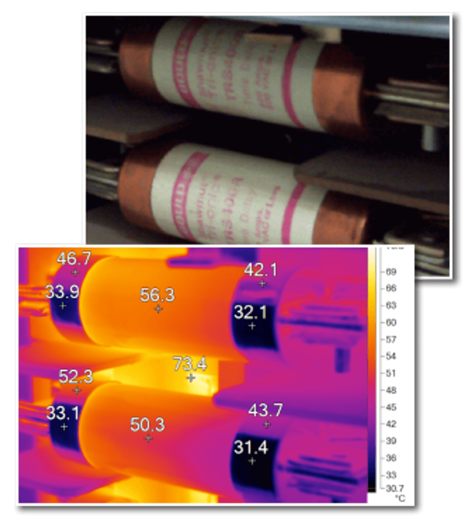
Figure 4: The top image shows two fuses in a three-phase fused disconnect panel; the visible light shows the fuses have white paper bodies, but polished copper end caps. In the bottom image, the fuse bodies emit infrared energy at a level showing 50°C to 56°C, but the fuses end caps have both low emissivity and high reflectivity, as portions of the end caps indicate temperature in the 40°C range, while other portions are reflecting infrared from in front of the panel, indicating temperatures in the 30°C range. The left end cap of the lower fuse show one spot reflecting infrared from the upper fuse, indicating 52.3°C. In reality, the entire length of both fuses is likely in the 50°C to 56°C range.