To perform the Rim & Face Method, you must:
- Mount the dial indicators fixtures.
- Measure the A, B, & C dimensions.
- Obtain as-found readings.
- Determine the vertical foot positions.
- Make vertical corrections.
- Make horizontal corrections.
- Re-measure and record final alignment values.
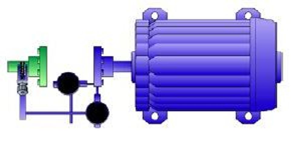
Mounting the dial indicator fixtures
To mount the fixtures follow these steps:
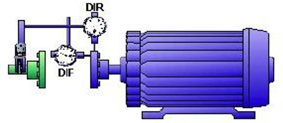
1. With the coupling broken, mount the fixture to the stationary shaft or coupling hub.
2. Span the coupling with a rod.
3. Rotate the fixture to 12:00.
4. Attach the face dial indicator. The dial indicator plunger must be centered for equal positive and negative travel.
5. Attach the rim dial indicator. The dial indicator plunger must be centered for equal positive and negative travel.
Fixture Mounting Precautions
Regardless of the specific hardware being used, the following precautions should be observed.
- Never attach the fixture to the flexible portion of the coupling.
- Maximize the sweep distance of the face dial indicator for the geometry of the machine being aligned. If the face dial contacts the coupling face directly, ensure the plunger of indicator contacts the coupling near its outer edge.
- Ensure fixtures are mounted at a position where rotation is possible. It is desirable to have 360 degrees of rotation.
Before obtaining alignment measurements, determine dial indicator bar sag of the rim dial indicator and ensure dial indicator readings are valid and repeatable. See Section 2 for details.
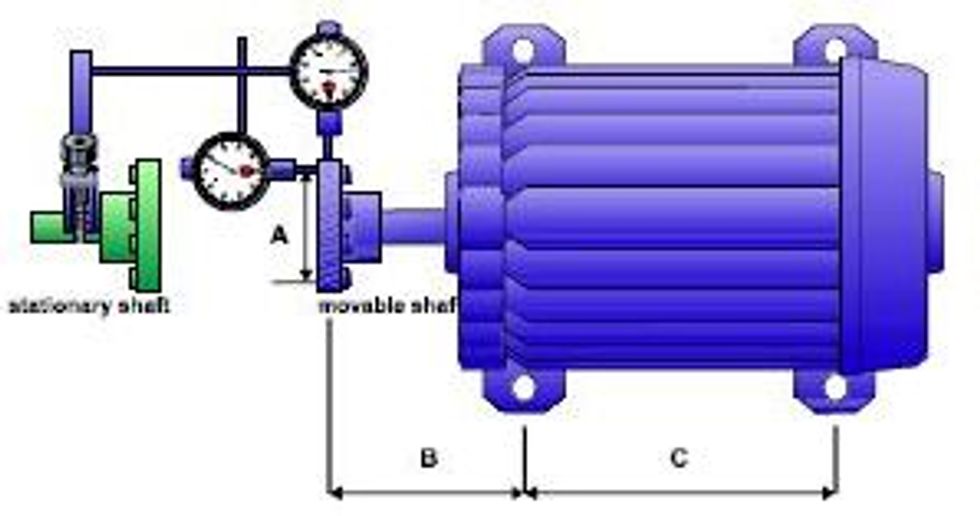
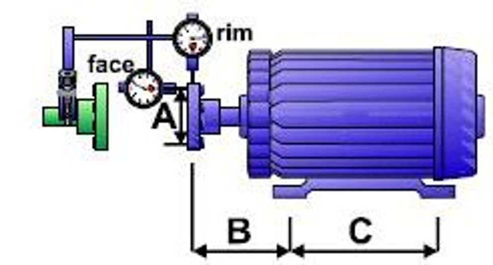
Measuring the A, B, & C dimensions

To measure the A, B, & C Dimensions, follow these steps.
1. The "�A"� Dimension is the diameter of face indicator travel. The �"A"� Dimension should be slightly less than the coupling diameter.
This is the most critical dimension.
Measure �"A"� very carefully.
2. The �"B"� Dimension is the distance from the rim indicator to the front foot bolt center. This dimension is measured parallel to the shaft.
3. The �"C�" Dimension is the distance between front and rear foot bolt centers. This dimension is measured parallel to the shaft.
Obtaining As-found Readings
To obtain a complete set of as-found readings, perform the steps below:
1. Rotate the dial indicators to 12:00.
2. Set the rim dial indicator to the positive sag value.
3. Set the face dial indicator to zero.
4. Record the setting of both dials at 12:00.
5. Rotate the dial indicators to 3:00.
6. Determine and record the reading on both dials.
7. Rotate the dial indicators to 6:00.
8. Determine and record the reading on both dials.
9. Rotate the dial indicators to 9:00.
10. Determine and record the reading on both dials.
11. Rotate the dials to 12:00 and ensure both dials return to their original setting.
Document as-found results using a format similar to that shown below.

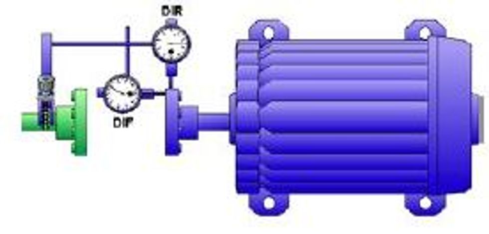
Measuring & Interpreting Vertical Misalignment
To measure vertical misalignment, perform the following steps:
1. Rotate the dial indicators to 6:00.

2. Set the face dial indicator to read zero.
3. Set the rim dial indicator to the sag value.
4. Rotate both shafts (if possible) to 12:00.

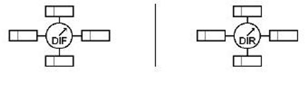
5. Record the DIR and DIF dial indicator TIR values.
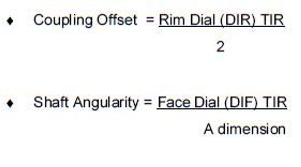
To determine offset and angularity from the 12:00 TIR�s, use the following rules:

Measuring & Interpreting Horizontal Misalignment
To measure horizontal misalignment, perform the following steps:
1. Rotate the dial indicators to 9:00.

2. Set both dial indicators to zero.
3. Rotate both shafts to 3:00.

4. Record the DIF and DIR dial indicator TIR values.
To determine offset and angularity from the 3:00 TIR�s,use the following rules:

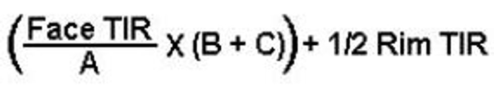
Calculating the front and rear feet positions

• Front foot position calculation:

• Rear Foot position calculation:

• Positive values mean the foot is high, shims must be removed.
• Negative values mean the foot is low, shims must be added.
Rim-Face Calculation Precautions
1. Ensure the rim and face dial indicator TIR�s are properly determined from the dials prior to performing calculations.
2. Be careful NOT to make mathematical errors when subtracting signed numbers.
3. Observe parentheses in the equations. Perform operations inside parenthesis first.
4. Do NOT make human errors substituting real values into the equations.
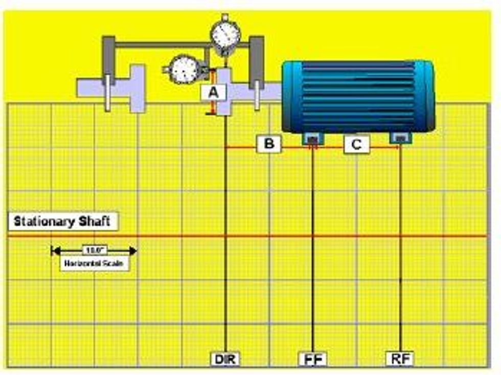
Constructing A Rim-Face Graph
To construct a scaled Rim-Face graph, perform the following steps:
1. Obtain graph paper with 10 divisions between bold lines.
2. Turn the graph paper so that the long side is horizontal.
3. Draw a horizontal line at the center of the page.
- This line represents the stationary shaft center and is drawn across the page midway down the graph dividing the page. It is helpful if this line is on top of one of the bold lines.
4. Determine the horizontal plotting scale.
- Always use the largest scale possible. Measure the distance from the stationary indicator plunger to the center-line of the rear feet of the movable machine. Standard graph paper is about 10 inches across. The largest horizontal scale will be the machine distance divided by the page width. Note your horizontal scale.
5. Make a vertical line on the extreme left of the horizontal line.
- This mark represents the point where the rim dial indicator contacts the shaft or coupling hub and is labeled: DIR.
6. Make a second vertical line representing the point along the shaft length of the front feet of the movable machine (FF).
7. Make the third vertical line representing the point along the shaft length of the rear feet of the movable machine (RF).
Upon completion of the steps above, the graph will look similar to the one shown below. For this example, the B and C dimensions both equal 10 inches.

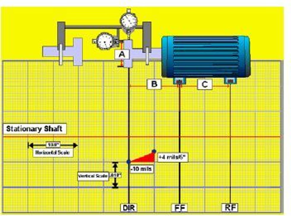
Plotting Offsets
After setting up the graph, the next step is to plot two offset points. One is the offset measured in the plane of the rim dial indicator (DIR). The other offset point is derived from the face dial indicator (DIF) reading and
the �A� dimension. To plot the offsets, perform the following steps:
1. Determine the vertical scale.
- The vertical scale is typically 1 mil (0.000�) per division. In cases of gross misalignment where the offsets will not fit on the page, a larger scale, such as 2-3 mils per division, is sometimes required.
2. Plot the offset from the rim dial indicator on line DIR.
- Use the horizontal line representing the stationary shaft centerline as the reference. All points above this horizontal line are positive (+) and all points below the line are negative (-).
- Ensure you divide the Rim Dial TIR by 2 to obtain an offset value.
3. Plot the second offset point using the shaft slope (Face TIR / �A� dimension).
- Plot this point counting from the DIR offset point!
In the rim-face graph example below, the DIR offset is -10 mils and the shaft slope is +4 mils over an A dimension of 5�.

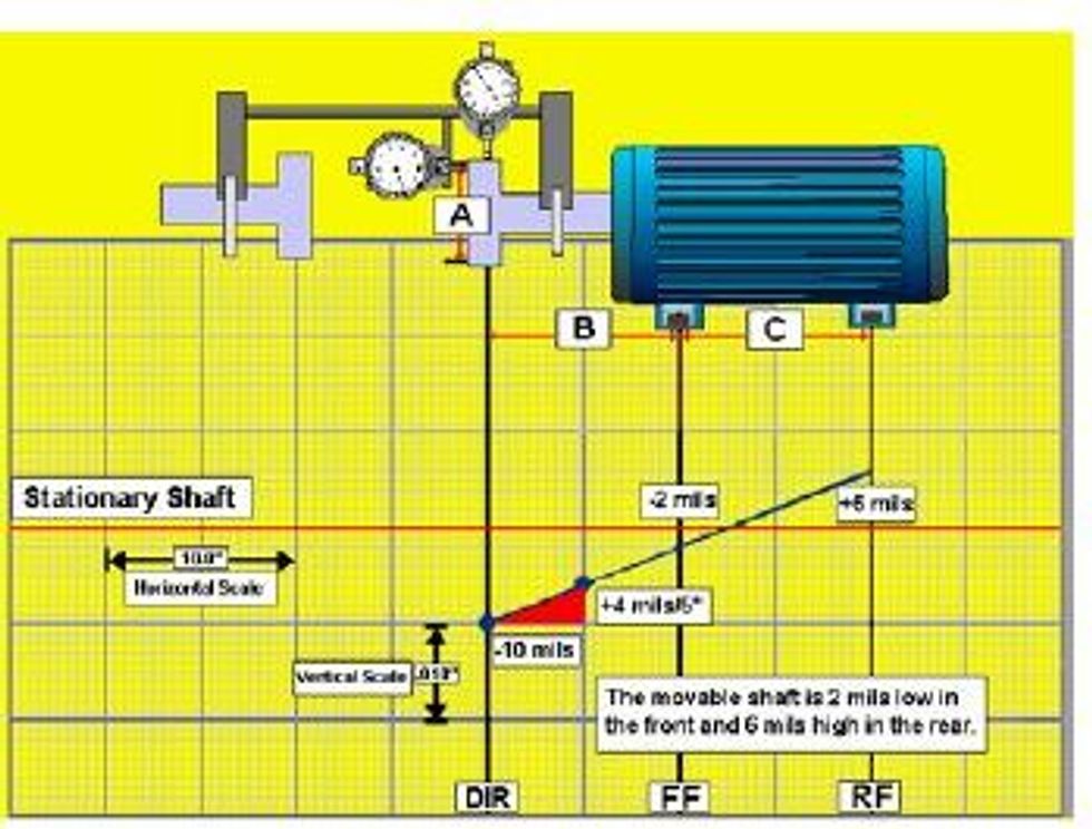
Determining Movable Shaft Position
After plotting the two points, to determine the movable shaft position perform the following steps:
1. Using a ruler or straightedge, draw a line through the two offset points that extends to the rear feet of the movable machine.
2. Count the number of squares in the plane of the front and rear feet to determine the position and corrections needed.
In the example below, the front feet of the machine are 2 mils low; shims need to be added. The rear feet are positioned 6 mils too high; shims need to be removed from both rear feet.

Rim-Face Graphing Precautions
1. Ensure proper horizontal and vertical scaling techniques are consistently used.
2. Always double check the position of vertical lines drawn to represent the DIR, FF, and RF.
3. Ensure the two plot points are properly determined from TIR�s.
4. Ensure positive offsets are plotted above the horizontal reference line and negative offsets are plotted below the line.
5. When interpreting the graph to determine the movable shaft�s front and rear feet positions in the ertical plane, observe the following rules:
- If the movable shaft is above the horizontal stationary shaft reference line the shaft is too high.
- If the movable shaft is below the horizontal stationary shaft reference line, the shaft is too low.
6. When interpreting the graph to determine the movable shaft�s front and rear feet positions in the horizontal plane, view the graph the way you view the machine, that is, standing behind the movable
machine facing the stationary machine. Also observe the following rules:
- If the movable shaft is above the horizontal stationary shaft reference line the shaft is positioned to the right.
- If the movable shaft is below the horizontal stationary shaft reference line, the shaft is positioned to the left.
Making vertical corrections
To correct vertical misalignment, follow the steps below:
1. Determine the vertical position of the movable machine using calculation and/or graphing techniques.
- Positive values at the feet mean that the movable machine is high, therefore you will remove shims.
- Negative values mean that the movable machine is low, so you will add shims.
2. Make shim changes to both front feet and both rear feet as needed.
3. Always check shim thickness with an outside micrometer. Precut shims aren't always what they're marked; many shim manufacturers designate shims with the �nominal� thickness.
4. Use consistent and correct torquing procedures.
5. As shim changes are made, check for and take precautions to avoid creating soft foot conditions.
Making horizontal corrections
To correct horizontal misalignment, follow the steps below:
1. Rotate the dial indicators to 9:00 and zero them.
2. Rotate both shafts (if possible) to 3:00.
3. Adjust the dial indicators to one-half values.
4. Move the front feet of the movable machine as you watch the rim indicator move to zero.
5. Move the rear feet of the movable machine as you watch the face indicator move to zero.
6. Repeat steps 4 & 5 until both dial indicators read zero.