In the paper industry, for example, enclosures, such as the drying hood, represent an optical barrier for the theodolite bar. Large distances between rolls in galvanization lines make the usage of telescope bars impossible. However, roll alignment is absolutely necessary. Figure 1 shows the effects of a nonparallel roll on the material web.

Figure 1: Effect of a nonparallel roll on the material web where a transversal force orthogonal to the production direction occurs. Whatever this force may do to the web, the consequences are negative for production output and quality. They may reach from small folds to web breaks and increased web movement. Furthermore, the web extension is nonsymmetrical (illustrated by the red line for higher tension and the green waves for lower tension), which leads to a nonsymmetrical winding of the web. Last but not least, the material itself is deformed, as shown by the orange rhombuses.
The transversal force caused by the misaligned roll stretches the web nonsymmetrically, deforms it and makes it move up, which results in the production of folds and web breaks. To prevent such a scenario, the rolls have to be aligned orthogonally to the machine’s reference line and parallel to each other. As previously noted, this can be a challenging task.
But let’s take a look at how this task can be performed using optical systems.

Figure 2: Determination of roll parallelism using traditional technology. A laser beam is set up alongside the machine axis and then deflected into the rolls to be measured. If the rolls are to be checked on separate levels or in housed areas, this measurement procedure is time consuming and the use of additional optical equipment in order to reach each roll represents a loss in accuracy.
In theory, after the machine’s axis has been picked up from reference marks 3 and 4 shown in Figure 2, the laser beam is deflected into the machine to measure the position of a roll. Therefore, a detector must first be placed on the operator’s side and then on the machine’s side. This process has to be repeated for every single roll, which makes it very time consuming.
In real life, machines can reach from the basement of a factory over several floors to the very top. In most cases, no optical access is available. In such cases, telescope bars can help align one roll to the next. Circumference measurements are also a possibility, but only if the distance between the rolls is not too high.
The bottom line is:
- Roll alignment is an absolute requirement to reach a high machine output while keeping the mandatory quality standards.
- The technologies available for roll alignment are limited in one way or another by the machine geometry.
It would be nice to have a system that makes it possible to accurately measure every single roll in the machine independent from the machine geometry and all rolls are measured very quickly to save production time.
The good news is: It is possible!
The key relies on a technology used for almost 100 years in aircrafts and later on in spacecrafts -- the gyroscope as part of the navigation system. Such gyroscopes keep their rotation axes unchanged due to mass inertia, even if their base is shifted. Figure 3 shows this physical phenomenon.

Figure 3: The gyroscope stays in the same axis while its base is being moved. This way an angular measurement along the rotation axis is possible, as shown on the right.
Three gyroscopes arranged along three dimensions in space (x, y, z) result in a measurement unit that can identify its relative position in space at any time. Using this so-called inertial measurement unit (IMU), aircrafts and spacecrafts can determine their flight attitude. The three roll, pitch and yaw angles give the pilot exact values about the aircraft’s position in space.
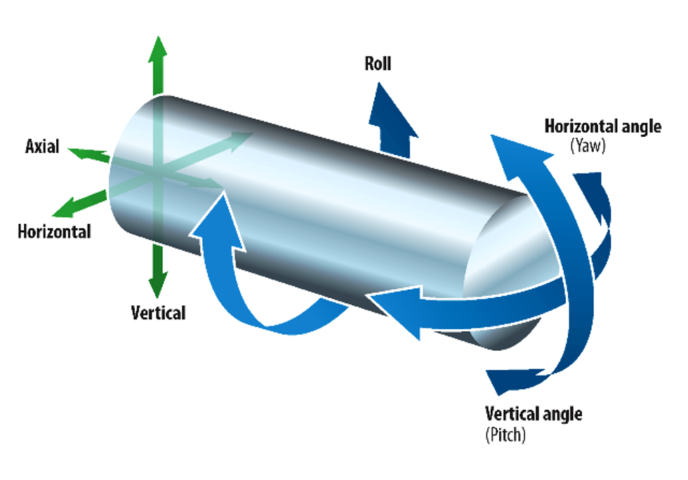
But where is the link between such navigational technology and the challenges of precise roll alignment? A detailed look at the rolls’ degrees of freedom in space will give us a hint. Figure 4 shows a roll and its positioning properties. Conclusion: The position of a roll in space is not so different from the one of an aircraft. The roll, pitch and yaw angles also can be used as an indicator of the roll’s position, just like the flight attitude.
Because it would make no sense to equip every roll in a machine with an IMU, a way to develop a measuring device with an integrated IMU that can be used on the roll’s surface to determine its position is needed. The solution is as ingenious as simple. By using the three orthogonally arranged gyroscopes in a frame with two parallel feet, a link between any surface and the IMU itself is created. The device is now ready to be moved along any surface and to record the angular changes during the movement. If the device is moved along a circle around the roll, its position can be calculated. It is not even necessary to move it along the full circle. A movement of 20 degrees around the roll angle is enough; a mathematical algorithm does the rest.

Figure 4: Illustration of a roll and its degrees of freedom in space. The roll angle defines the rotation axis itself; the pitch angle represents the vertical position of the roll; the yaw angle represents the horizontal position. With the three angles, roll, pitch and yaw, the roll’s position is determined in the same way as the flight attitude.
Figure 5 shows the IMU within its frame and the two feet (left) and the way to use it on a roll (right).


Figure 5: The image on the top shows the IMU and its gyroscopes in blue. Each gyroscope measures around its rotation axis shown in red. The image on the right shows the measurement process of a roll. The inertial measurement unit is placed on the roll’s surface. By moving the device along a circle on the roll, the geometrical position of the roll is measured. Unlike traditional systems, the IMU does not need any line of sight to or between the rolls.
The benefits of such a system used for roll alignment are huge: No line of sight is required. Measurements over several layers and high distances in enclosed machine parts are no longer challenging. All restrictions from optical or mechanical systems are removed and the requirements to measure all rolls in the machine with the same accuracy and within an appropriate time are fulfilled.
Using this technology, it is possible to measure and align complete machines during a regular maintenance shutdown. The returns include higher production output and increased product quality by preventing the negative effects of misaligned rolls.
 Christian M. Reidler, Engineer, M.Sc. PRÜFTECHNIK Alignment Systems GmbH, Germany. After graduating from the Technical University of Munich as an engineer with the core area in measurement systems, he worked as an International Sales & Application Engineer in high end measuring and alignment services for the heavy industry. In 2011, he graduated additionally in Management and Business Administration with a Master of Science. His machine knowledge and long-term international experience combined with business efficiency make him a competent consultant in multiple alignment issues. www.paralign.info
Keep reading...Show less


 Christian M. Reidler, Engineer, M.Sc. PRÜFTECHNIK Alignment Systems GmbH, Germany. After graduating from the Technical University of Munich as an engineer with the core area in measurement systems, he worked as an International Sales & Application Engineer in high end measuring and alignment services for the heavy industry. In 2011, he graduated additionally in Management and Business Administration with a Master of Science. His machine knowledge and long-term international experience combined with business efficiency make him a competent consultant in multiple alignment issues.