The story begins along the east bank of the Arkansas River at Oklahoma Gas and Electric's Muskogee Generating Station, about three miles east of Muskogee, Oklahoma. The station consists of three large coal fired units, each producing approximately 505 net megawatts, and one smaller 180 net megawatt gas fired unit.
On Muskogee Unit 4, one of the coal fired units, condensate is pumped by two 60% capacity pumps driven by two identical Westinghouse 1000 HP condensate pump motors. The motors are vertical Westinghouse 6808 P30 frame, 4160 Volt, 3 Phase, 60 cycle motors with a 1.15 service factor.
In October of 2006, Operations alerted the Reliability Technician of a potential problem with the MK4B Condensate Pump. The technician proceeded immediately to the pump to determine if the vibration had increased. Indeed, the vibration level had doubled since the last monthly route data had been uploaded two weeks earlier. A doubling of the amplitude was an obvious indication that there had been a change in machine condition. Was the change in the pump, or the motor, or both? This is usually the first question asked, quickly followed by, "How long will it last?"
One of the easiest ways to answer the first question is to divide and conquer. Uncouple the motor. Run the motor solo and see if the vibration goes away. If the vibration goes away, the problem is most likely in the pump. If the vibration is still higher than normal, the problem is probably in the motor.
If Dispatch could allow the unit to come to half load, this fairly common troubleshooting technique could cut the problem in half. As luck would have it, system needs required the unit to remain at full load, if at all possible. So, other methods had to be devised to diagnose the problem.

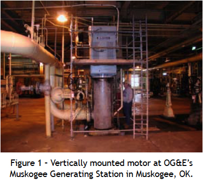
The top of the vertically mounted motor is approximately ten feet above floor level (see Figure 1). The bottom of the pump is almost twenty feet below floor level. Figure 2 shows a multi-stage pump being lowered into position. Without permanently mounted vibration probes, it was impossible to get direct measurements from the pump. We took several readings on the motor and along the motor base, and we used a fishtail to obtain shaft readings adjacent to the coupling and stuffing box.

The highest readings were from the motor outboard. The amplitudes gradually decreased as the probe was moved from the top of the motor to the floor, which might lead one to conclude that the problem was in the motor, since this was where the highest readings were. But, past experience had shown that sometimes the tail wags the dog. In this particular arrangement, a vibration caused by forces in the pump can cause the top of the motor to move back and forth as the whole assembly pivots about the floor, similar to a lever and a fulcrum. Or, could it be just something terribly wrong in the top of the motor? Frequency analysis would help to identify the problem.
The spectra contained a peak close to 0.5x running speed that was higher than the running speed peak (see Figure 3). There was also what appeared to be a harmonic at 1.5 x running speed. These ½ harmonics are often associated with rubs. The most likely place for a rub would be the impeller rubbing in the pump. Perhaps, there was some debris in the suction?

The sub-synchronous frequency was 750 cpm, or .4x running speed. The upper frequency of interest was 2825 cpm, or 1.6x running speed. Neither was an exact ½ multiple. The possibility remained that this might be the cage frequency of the lower bearing in the motor. However, since most of the vibration was in the top of the motor, this theory was discounted.
Another possibility was that the frequencies in question were non-synchronous vibration being excited by the pump or the motor. Researching the OEM manuals revealed the pump natural frequency between 500 cpm and 800 cpm. This could actually be a resonance.
There were now three clues leading us to the conclusion that the problem was with the pump, possible resonance, possible rub, and possible fulcrum effect. The next day the vibration doubled again and Dispatch agreed to allow the unit to come to half-load and remove the pump from service.
The pump inspection revealed extensive damage. It was a complete wreck. Something had apparently gone through the pump and destroyed several impellers (see Figure 5). The first stage cast iron housing was broken off of the pump. All of the cutlass bearings were in need of replacement and one had seized to the journal and was spinning in the housing. Due to the machine work on the journals and bearing housings and the lead time to order impellers, we decided to send the motor in for a routine clean, dip, and bake.The motor inspection revealed no obvious defects. All clearances and run-outs were within acceptable tolerances. There were no rub marks or evidence of any shorting on the rotor or in the winding. The bearings had only normal wear and the journals were in good shape.

The motor inspection revealed no obvious defects. All clearances and run-outs were within acceptable tolerances. There were no rub marks or evidence of any shorting on the rotor or in the winding. The bearings had only normal wear and the journals were in good shape.
The motor was steam cleaned, and the winding dipped and baked. The rotor went through the balance machine before reassembly. The motor was test run on a test pad at full voltage. The vibration amplitude exceeded acceptance standards. Trim balancing was attempted and the test run repeated without improvement. At this point, there was a pause to take another look at the data and develop a new plan of action.
Not only were the overall levels too high, there was a significant 2x component with some 3x in the spectrum. Looseness was an immediate speculation. The carrier bearing in the outboard of the motor is a critical fit, and any taper in the journal or looseness in this fit will cause excessive vibration in the top of the motor. The carrier bearing had not been removed during disassembly due to the meticulous effort required to maintain this critical fit.
We decided to pull the rotor and remove the carrier, but the journal and bearing were well within tolerances. All clearances and run-outs were re-checked and found to be acceptable. We found nothing to explain the high vibration. The motor was carefully reassembled and test run.
Vibrations were still high, with a 2x running speed frequency that was higher than the running speed component and there was still some 3x. Knowing that the motor had been scrutinized with a fine tooth comb twice, suspicion shifted to the shaft. Since the pump had suffered such a catastrophic failure, perhaps some of the energy transferred through to the shaft and damaged it. If nothing else, maybe a few simple tests would eliminate the possibility of a bad shaft.
The first thing was a simple bump test. To everyone's surprise, it rang like a bell around running speed and at two times running speed, (Figure 6). This natural frequency had not always been present. Where did it come from? What had changed? Either the mass or stiffness had to change in order to shift the natural frequency. A crack in the shaft could possibly explain a change in stiffness resulting in a change of the natural frequency. However, neither dye penetrant nor ultrasonic testing uncovered any evidence of a crack in the exposed portion of the shaft. If there were a crack, it was where these tests could not detect it.

Any further testing would require pressing the iron off of the shaft. Besides being expensive, this could easily ruin the shaft. Well, either the shaft was already ruined, or it was going to be ruined in order to find out if it was ruined. We decided to stop doing any more testing and not take excessive care to save the shaft (see Figure 7). Instead, we would just build a new shaft.

Measurements were taken from the old shaft and a new one was turned from similar materials. The new one was bump tested before the rotor iron was pressed on, and again after the assembly was complete. These tests showed no natural frequencies near running speed or running speed harmonics. The rotor was balanced. The motor was assembled, once more placed on the test pad, and, after a slight trim balance, the motor passed acceptance testing. The motor was finally placed on a truck, the rotor blocked to prevent any movement, and shipped back to the Muskogee Power Plant to be placed in service.
Motors are routinely run uncoupled for ac-ceptance testing before placing them in service. This establishes a chain of quality custody and a new baseline data for future comparison. If the motor does not pass acceptance, either something happened during transit, the motor base has a problem, or there is some on-site assembly problem because the shop tests prove the motor to be fine.
Well, as you might have already guessed, when this motor was run uncoupled for acceptance, it failed. Normally, a slight balance adjustment will allow a rebuilt motor to meet the acceptance criteria. This motor did not respond predictably to weight movements., and further diagnosis discovered symptoms other than imbalance. There was still some 2x and a little 3x in the spectrum, with the majority of vibration at running speed. Figure 8 shows the motor being tested on its own base and foundation.

There was no obvious shipping damage. The motor was uncoupled, so there was no misalignment. Imbalance had been ruled out by process of elimination. The base and/or the foundation were really all that were left. A visual inspection of the base revealed that a couple of nuts were not even touching the base. In fact, the blade of a pocket knife could fit in between the nut and the base. The grouting was also cracked and deteriorating. A machinist's level placed on the base determined a severe out of level condition, so 40 mils of shims were required to level the base. After this temporary repair, the motor was once more run uncoupled. Figure 9 shows the shim pack under the bottom right hand corner of the base plate.
The vibration was greatly reduced, but not yet within expected readings for an unloaded motor. Most of the vibration was now at running speed, and phase analysis indicated ac ouple imbalance. Correcting the couple imbalance would require weights to be placed in both ends of the rotor.

Even though this rotor had been balanced at the motor shop in a balancing machine, all symptoms suggested imbalance. Experience has shown that this is not uncommon in a vertical machine. In the balancing machine, the rotor is balanced when mounted horizontally. Then, when it's turned upright to the vertical position, a couple imbalance is often observed. This, plus the fact that the motor is now sitting six feet above the floor on a base that allows much more movement, means much less force is needed to create unacceptable levels of vibration.
Removing a cover allows easy access to the outboard end of the motor, where there are provisions for balance weights. However, access to the lower end of the motor is rather difficult. The only way to attach weights is to worm a hand and arm through and around to gain access to the cooling fan. Dispatch was now calling for load. Luckily, with historical balancing data in hand, one run was all that was needed to balance the rotor.
The vibration was now at or below historical levels, so the motor was coupled to the pump. A performance test was conducted to evaluate the pump repair. This test proved the pump to be in good shape. Baseline vibration data was collected and the machine was returned to service (see figure 10).

The unit was given back to Dispatch 29 days after the first problem was discovered. The old grouting was removed, the base was leveled, and new grout poured at the next scheduled unit overhaul. While this was a very challenging case, not all machines are so difficult all the time. Rarely do so many problems exist at the same time on the same machine. Complex problems require complex problem solving. Each machine is different and that's what makes this job so rewarding and keeps life so interesting.