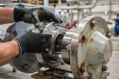
Mechanical seals are often small compared with the pump, driver, coupling, baseplate, piping system, or control system. Yet anyone who has spent time around rotating equipment knows that seals can have a much larger impact than their size suggests. A mechanical seal is not just a wear part. It is a containment device, a reliability component, an emissions-control device, and in many services, a critical safety barrier. At its simplest, a mechanical seal contains process fluid where a rotating shaft passes through a stationary casing. In real plant operation, that simple function becomes extremely important. A seal may be the only component preventing a hydrocarbon, toxic fluid, hot liquid, corrosive chemical, or environmentally sensitive product from leaking to atmosphere. When a seal performs well, it is easy to forget it exists. When it fails, the consequences can include unplanned maintenance, environmental release, equipment damage, production loss, personnel exposure, and in some services, fire or safety risk.
Seals are also not inexpensive components. A wet seal repair can cost approximately $30,000 to $70,000 per cartridge depending on the design, materials, failure mode, and type of seal. Specialized dry gas seal repairs can exceed $100,000 per repair. New seal designs can cost even more depending on the application, pressure, temperature, service, emissions requirements, and engineering involved. Plants may also need to carry spare cartridges for critical equipment, adding further inventory cost. When repeated failures occur, the lifecycle cost can quickly move beyond the seal itself and include downtime, troubleshooting, lost production, emergency maintenance, and environmental response.
For this reason, seal reliability should not be treated as only a maintenance issue. It directly affects equipment availability, operating risk, and lifecycle cost. A seal failure may appear to be a localized pump problem, but in many cases it is a symptom of a larger system issue. A mechanical seal works through the interaction of two highly finished faces. One face rotates with the shaft, while the other remains stationary with the seal gland or housing. These faces are pushed together by spring force and hydraulic closing force from the sealed fluid. The faces are manufactured to a very high degree of flatness, and the gap between them during operation is extremely small.
The important point is that most wet mechanical seals are not intended to run completely dry. Reliable operation depends on maintaining a very thin, stable fluid film between the rotating and stationary faces. This film provides lubrication, removes heat, and helps prevent destructive face contact. In many ways, the fluid film is the heart of the seal. The challenge is that the film must be thin enough to control leakage, but stable enough to lubricate and cool the faces. If that film is disturbed by flashing, vaporization, solids, contamination, coking, poor cooling, or unstable pressure, the faces can overheat, wear, distort, crack, blister, coke, or fail. This is why simply replacing a failed seal cartridge without understanding the operating environment often leads to repeated failures.


Seal arrangement and seal support plans are critical because they help create the environment in which the seal faces operate. Single seals are often used in clean, non-hazardous, and lower-risk services where minor leakage does not create a significant safety or environmental concern. Dual seals are used where the consequence of leakage is higher, such as hazardous fluids, volatile hydrocarbons, toxic services, dirty services, or environmentally sensitive applications. Dual seals may be arranged in tandem, back-to-back, or face-to-face configurations. The correct arrangement depends on the fluid, pressure, temperature, leakage philosophy, safety requirements, and whether the system uses a buffer or barrier fluid. The objective is not only to seal the pump, but also to provide an additional layer of protection between the process fluid and atmosphere.
API 682 seal plans provide standardized methods to flush, cool, lubricate, pressurize, and monitor the seal environment. Although these plans are sometimes viewed as auxiliary piping, they are much more than that. They directly influence the fluid film, seal face temperature, vapor margin, contaminant removal, and leakage containment.
Plan 52 is commonly used with dual unpressurized seals. It uses an external reservoir containing buffer fluid between the inner and outer seals. This arrangement can collect leakage from the inboard seal and provide containment before leakage reaches atmosphere. However, because it is unpressurized, the inboard seal still depends heavily on process-side conditions.
Plan 53B uses a pressurized barrier fluid system with a bladder accumulator. The barrier fluid is maintained at a pressure higher than the seal chamber pressure. This helps direct clean barrier fluid across the inboard seal faces and reduces the chance of process fluid entering the seal interface. In challenging services, especially where safety, emissions, or fluid stability are major concerns, this can provide important reliability and containment benefits.


The difference between an unpressurized and pressurized dual seal system is not just cost or complexity. It is about the condition of the fluid film and the direction of leakage. In an unpressurized system, process leakage tends to move toward the buffer system. In a pressurized system, clean barrier fluid is intended to move toward the process. This distinction is especially important in light hydrocarbon services, where fluid can be close to its vapor point. If heat at the faces causes the liquid film to flash to vapor, lubrication and cooling can be lost very quickly.
Improving seal reliability starts by treating the seal as an engineered system, not just a cartridge. Practical checks include maintaining clean flush or barrier fluid, verifying seal pot level and pressure, confirming accumulator pre-charge, ensuring coolers are working, checking that vents are properly used, and confirming that orifices or restrictions are not plugged. For services with solids, coke formation, or polymerizing fluids, the flush strategy and face materials become even more important. Mean time between repairs improves when plants learn from repeated failures. A seal failure report should not only state that the faces were damaged. It should ask why they were damaged. Was the issue dry running, flashing, contamination, high temperature, poor lubrication, pressure reversal, installation error, vibration, process upset, or operation outside the intended envelope?
Mechanical seals may be small, but they carry major responsibility. They protect people, equipment, the environment, and production. The key lesson is simple: seal reliability is not achieved by the cartridge alone. It depends on the fluid film, seal arrangement, support plan, process conditions, maintenance practices, and how the equipment is operated. When these elements are treated as one system, seal performance improves. When they are treated separately, repeated failures and high costs often follow.