Introduction
Some sensors respond to vibratory displacement or position, others respond to velocity. Here, we’re talking about sensors that respond to vibratory acceleration, the second time derivative of displacement to changes in velocity -- accelerometers.
Whereas a microphone responds to changes in pressure, an accelerometer senses the motion of some structure to which we’ve attached it. Our accelerometer converts that motion into an electrical signal. We measure that signal to determine the acceleration of our structure. OK?
Particularly at higher frequencies (e.g., 1000 Hz), our displacements and our velocities are so small that measuring them is difficult. Yet accelerations and thus, accelerometer output signals, may be reasonably large and fairly easy to measure.
Over the past century, machinery speeds (and thus vibration frequencies) have risen tremendously. But while use of displacement and velocity sensor has declined, the use of accelerometers (also spurred by significant accelerometer improvements) has risen. Figure 1 shows one significant improvement: Accelerometers have become much smaller and lighter, much less affecting the vibration they are emplaced to measure. Some accelerometers are self-generating, others require a DC power supply, but with all, sensitivity is given in mV/g.

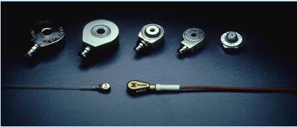
Figure 1: Accelerometers have gotten smaller (Photo courtesy of Endevco, now Meggitt)
Figure 2 shows that they all resonate at some natural frequency (fn) and they all over report vibrations around fn. Don’t try to use them above 0.1fn or 0.2fn.

Figure 2: Effect of a too low accelerometer fn
Tri-Axial Accelerometers
That’s a misnomer. Accelerometers are single-axis devices. However, three accelerometers (mutually perpendicular directions) in one case are called tri-axial. Align it with your machine’s fore-and-aft, vertical and left-right axes to measure fore-and-aft, vertical and left-right motions. From such an assembly, as seen in Figure 3, come three acceleration signals, often through a delicate multi-pin connector. Those three signals usually differ greatly.

Figure 3: Tri-axial accelerometer (Photo courtesy of Dytran)
The Handheld Accelerometer
Occasionally, you will want to measure motion at a series of locations without attaching your accelerometer. Figure 4 suggests a handheld accelerometer, an ordinary accelerometer with an extra long, sharp pointed accelerometer stud.

Figure 4: The handheld accelerometer
Cable Disconnects
Figure 5 suggests connector complexity. Considerable skill is required to properly attach connectors. Your people probably have not had sufficient time to develop that skill. The data you gather is so valuable that you need the best possible cables. When you even suspect a cable is bad, destroy it!

Figure 5: Cable disconnect (Image courtesy of Kistler)
Accelerometer Mechanical Errors
Each millivolt of signal from our accelerometer should represent a specific magnitude of acceleration, at all frequencies. Thus, we certainly will calibrate our sensors (Part 3). However, all sensors do, unfortunately, respond to all inputs.
Table 1 shows factors that can upset the ideal 1:1 relationship. The left column factors are those that affect the sensor. Those in the right column affect signals on the cable.
Table 1 Error-producing factors

Sometimes, mechanical errors can result from other factors, like dropping the accelerometer, see Figure 6. If that does occur, be sure to “red tag” that accelerometer. Don’t use it until thoroughly recalibrated it over its entire frequency range (to be discussed in Part 3). Single frequency checking is not sufficient.

Figure 6: Avoid dropping accelerometers
Similarly, don’t remove a cemented or epoxied accelerometer with a hammer. Soften the cement, then carefully twist it off. Use an appropriate solvent to soften any remaining cement and wipe off the remainder. Don’t scrape the accelerometer base!!!
We want our accelerometer’s contact with its mounting surface to be flat and smooth. But peaks (asperities) occur on accelerometers and on mounting surface contacts. We tighten the mounting screw, which flattens the asperities, leaving dips, cavities and air pockets. Oil in those pockets couples better, so before we screw on our accelerometer to attach it, we apply a bit of light oil.
Avoid Accelerometer Bracket Resonances
Suppose we want to measure vibration parallel to a surface. We need a bracket, something like Figure 7. Our bracket’s first natural frequency fn should be at least three times (five times or even 10 times is better) the highest forcing frequency ff. One or two gussets will help stiffen the bracket.

Figure 7: Avoid bracket resonance
Mounting Devices
Figure 8 shows various studs, attachment pads, etc., used for mounting accelerometers onto the machine you’ll be monitoring. Two in the rear are electrically insulated (to prevent “ground loops” - see Part 2 of this series). Cement or epoxy B and B’, as shown in Figure 8, onto structures you’ll investigate, then screw your accelerometer into place. Stud mounting A and A’ gives your accelerometer the stiffest and most intimate contact with the machine you’re investigating. Accelerometer and flat mounting surface must be clean; a little oil fills microscopic voids and stiffens the connection.

Figure 8: Attachment devices
Mounting Method Effects
Accelerometers can be stud-mounted to permanent magnets for attachment to steel machinery. This works, although not as well as a “regular” stud mounting. Stud mounting gives the widest flat response range of frequencies and, thus, is safest to use.
Temperature Changes Affect Sensitivity
Sensor sensitivity, unfortunately, varies with temperature. How much? This requires specialized calibration (to be covered in Part 3).
Lateral or “Cross-Axis” Sensitivity
Motion sensors are supposed to respond only to motion (x axis in Figure 9) perpendicular to their bases. Unfortunately, they respond a bit to y and z motions.

Figure 9: Accelerometer’s lateral sensitivity
Remember that an accelerometer’s sensitive axis is perpendicular to the base.
Protect Accelerometers
Particularly around paper and similar manufacturing where strong chemicals splash and spray, we need to keep our sensors dry. Hence, the “boot” in Figure 10.

Figure 10: Protective boot (Photo courtesy of Dytran)
Conclusion
In Part 1 of this series on accelerometers, our concern has been mostly on the mechanical aspects. Next, our emphasis will be on the associated electronics.
