As predictive maintenance teams in industrial facilities strive for a more complete picture of their equipment’s health, high frequency vibration measurements have become a crucial addition for identifying faults, such as motor and pump bearing defects and gear tooth inconsistencies in high-speed gearboxes. As a result, there is an upsurge in demand for vibration sensors with a high frequency response.
Hooke’s Law and the Spring-Mass Harmonic Isolator
What determines the resonant frequency (and therefore high frequency response) of an accelerometer? For that answer, a look into the field of physics and the spring-mass harmonic isolator is required.
A spring-mass harmonic isolator consists of a spring hung vertically from a support structure. A weight is attached to the end of the spring. By pulling the weight down and then releasing it, the weight/spring assembly will oscillate evenly, both in speed and distance, back and forth across an equilibrium position, recreating the oscillation of a sinusoidal wave.
While the amplitude of the resulting oscillations can be theorized using Newton’s second law of motion (F=ma), the primary interest of this article is the speed of the resulting oscillations. This speed can be theorized using Hooke’s law. In the late 1670s, Robert Hooke proclaimed that natural/resonant frequency is a function of stiffness and mass, as seen in the following formula. In the spring-mass harmonic isolator example, the mass of the weight and the stiffness of the spring are predetermined, so the assembly’s oscillation speed cannot be altered unless either the spring or the weight is switched out for an alternative.
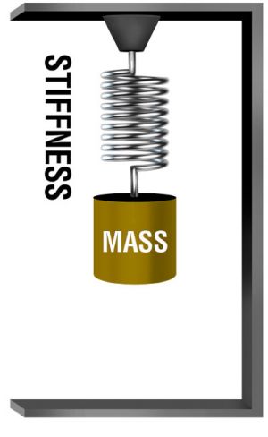
Figure 1: A spring-mass harmonic isolator best describes Hooke’s law

As the formula shows, resonant frequency and mass have an inverse relationship, while resonant frequency and stiffness have a direct relationship. In the world of accelerometers, the mass of the weight correlates to the mass of the accelerometer, while the stiffness of the spring correlates to the stiffness of the accelerometer’s mounting. To achieve high frequency measurements, an accelerometer must be as small as possible and have as stiff of a mounting methodology as possible. Each of these two factors is explored in detail in the following sections.
Factor #1: Stiffness of Sensor Mounting Methodology
There are several common methodologies used for vibration sensor mounting. These include stud mounting, adhesive mounting, use of a mounting pad and use of a magnet. Here are the characteristics for each mounting methodology:
Stud Mounting
- Maximum Frequency Response: Stud mounting an accelerometer directly to a piece of equipment provides the stiffest possible mounting and, therefore, the highest possible frequency response from the sensor.
- Equipment Modifications/Permanency of Installation: To stud mount a sensor to equipment, it is necessary to spot-face a smooth surface and then tap a pilot hole to fit the sensor’s mounting thread. Once removed, there is still lingering evidence of past sensor mounting.
- Can Install on Curved Surfaces: Stud mounting a sensor on a curved surface is not possible.
Adhesive Mounting
- Maximum Frequency Response: Mounting an accelerometer with adhesive directly to the equipment provides the second stiffest mounting methodology. Frequency response is reduced only slightly, about 10 to 15 percent, compared to a stud mounted accelerometer.
- Equipment Modifications/Permanency of Installation: An adhesive mounted accelerometer can be easily removed with the appropriate dissolving agent for the adhesive. Once removed, there is no evidence of past sensor mounting.
- Can Install on Curved Surfaces: Adhesive mounting a sensor on a curved surface is not possible.
Mounting With a Mounting Pad
- Maximum Frequency Response: Mounting pads can be adhesively bonded or welded to the equipment’s surface. Then, the sensor can be stud mounted to the mounting pad via the tapped hole in the pad. This type of sensor mounting is considered a midway point between the stiff methodology of stud mounting and the flexible methodology of magnet mounting. Frequency response will be reduced by approximately 35 percent compared to stud mounting.
- Equipment Modifications/Permanency of Installation: While a weld mounted pad is a relatively permanent installation, an adhesive mounted mounting pad can be easily removed with the use of an appropriate dissolving agent for the adhesive.
- Can Install on Curved Surfaces: Mounting a sensor on a curved surface with a mounting pad is not possible.
Mounting With a Magnet
- Maximum Frequency Response: Mounting an accelerometer with a magnet is a very flexible mounting methodology that will significantly degrade the sensor’s high frequency response by as much as 80 to 85 percent.
- Equipment Modifications/Permanency of Installation: The lack of required equipment modifications and the temporary nature of the installation are the reasons why magnet mounting is used in many applications. Magnet mounting offers the most convenient method of temporary sensor installation for route-based measurements and data collection.
- Can Install on Curved Surfaces: Magnet mounting a sensor on a curved surface is possible when a dual rail magnet is used.

Figure 2: Four common mounting methodologies for accelerometers
Factor #2: Sensor Mass
Sensor manufacturers continue to make smaller and smaller accelerometers in order to satisfy customers’ requests for sensors capable of high frequency measurements. This effort is challenging because manufacturers must balance the small size with the need for a rugged sensor that can withstand harsh environments.
Most industrial customers require:
- Robust Housing: In the world of industrial accelerometers, the robustness of the sensor’s housing is not determined by one single factor. Rather, it is determined by the housing material, the level of seal the housing provides and the electrical isolation of the housing. Most industrial accelerometer housings are 304 or 316 stainless steel and hermetically sealed in order to withstand chemical exposure and wide operating temperature ranges. An isolated case housing allows an accelerometer to be mounted on equipment with poor electrical grounding without running the risk of signal contamination. This isolation is typically achieved with the use of a Faraday cage, a continuous enclosure around the sensor’s electronics to repel noise.
- Rugged Connectors: Connectors must be able to withstand repeated use in harsh conditions. Military-style connectors are preferred, as they, along with their mating cables, can withstand extreme conditions.
Despite the challenges, sensor manufacturers have been able to successfully shrink the size of industrial accelerometers to about the size of a quarter. For example, some high frequency triaxial accelerometers measure just 0.95 inch by 0.95 inch and have a 13kHz frequency response on all three axes, isolated stainless steel case housing and rugged connectors.

Figure 3: A triaxial accelerometer with a footprint less than one inch square and a 13kHz frequency response on all three axes
Conclusion
High frequency measurements are gaining prominence as industrial predictive maintenance teams seek ways to get the most comprehensive look at the health of assets. The size of the sensor and the stiffness of sensor mounting methodology are the two most important factors contributing to a sensor’s ability to successfully provide high frequency measurements.

2017 Solution Award Winner
Asset Condition Management
High Frequency Triaxial ICP® Accelerometer


