There are specific issues with defining the philosophy of motor management. The most important is that many view motor management as energy management; others view it as motor testing, storage, greasing or some other function. These limited definitions are wrong and will destroy a program before it is started.
Why? Because they are merely functions and don't include a long-term philosophy. A true motor management program and philosophy will have both immediate impact and long term results.
Therefore, a more accurate definition of motor management is required:
Motor system maintenance and management is the philosophy of continuous improvement of all aspects of the motor system from incoming power to the driven load. It involves all components of energy, maintenance and reliability from system cradle to grave.
This provides the outline for any true motor management program which is intended to extend the useful life of the motor system, combined with continuous improvement and availability of the system. In addition, the focus is back on a systems approach, so that the system includes: Incoming power and distribution; Controls; Motor; Coupling; Load; and, Process. A full view of the system is sorely lacking in most programs.
In this article, we will discuss the motor system components and how issues within each component can affect the system, as well as some of the key issues and a few of the technologies used to evaluate those conditions.
While the past articles in this series have focused on testing as it relates to the electric motor (also called the electric machine) the purpose of this article is to expand the series to include testing and managing the complete system.
Incoming Power
 Starting from the incoming power to the load, the first area that would have to be addressed is the incoming power and distribution system.
The first area of issue is power quality and then transformers. Power quality issues associated with electric motor systems include, but are not limited to (there are many issues, so we are just covering the common ones here):
• Voltage and current harmonics: With voltage limited to 5% THD (Total Harmonic Distortion) and current limited to 3% THD, current harmonics carry the greatest potential for harm to the electric motor system;
• Over and under voltage conditions: AC induction motors and most modern drives are designed to operate at no more than +/- 10% of the nameplate voltage.
• Voltage unbalance: Is the difference between phases with a maximum of 5% voltage unbalance and recommended less than 2%. The relationship between voltage and current unbalance varies from a few times to many times current unbalance as related to voltage unbalance, motor design and other power quality issues in the system. The relation can be anywhere from 3x to over 20x voltage to current with the higher multiplier being related to such things as power factor differences between phases, impedance, motor load, etc. In a ‘perfect' system, the current unbalance is limited to 7x, under full load, per the NEMA MG-1 standard.
• Power factor: The lower the power factor from unity, the more current the system must use to perform work. Signs of poor power factor also include dimming of lights when heavy equipment starts.
• Overloaded system: Based upon the capabilities of the transformer, cabling and motor. Detected with current measurements, normally, as well as heating and over-heating issues. The primary tools used to detect problems with incoming power include power quality meters, electrical signature analysis and voltage and current meters. Knowing the condition of the motor system power quality can identify a great many phantom problems.
Transformers are one of the first critical components of the motor system. In general, transformers have fewer issues than other components in the system. However, each transformer usually takes care of multiple systems in electric motor and other electrical systems.
Common transformer problems include (oil filled or dry-type transformers):
• Insulation to ground faults;
• Shorted windings;
• Loose connections;
• Electrical vibration/mechanical looseness; and,
• Overheating, arcing or partial discharge in oil filled transformers.
Test equipment used for monitoring the health of transformers include but are not limited to:
• Motor Circuit Analysis (MCA) for grounds, loose/broken connections and developing shorts;
• ESA for power quality and late-stage faults;
• Infrared analysis for loose connections;
• Ultrasonics for loose connections, severe faults and bushing problems;
• Insulation testers for insulation to ground faults;
• Turn-to-Turn Ratio meters for winding shorts; and,
• Oil analysis for most conditions in an oil-filled transformer.
MCC's, Controls and Disconnects
 The motor control or disconnect provides some of the primary issues with electric motor systems. The most common for both low and medium voltage systems include:
• Loose connections
• Bad contacts including pitted, damaged, burned or worn
• Bad starter coils on the contactor
• Bad power factor correction capacitors which normally results in a significant current unbalance.
Additional systems include AC and DC drives, soft starts, amplifiers which we will address in future articles.
The most common test methods used for evaluating controls include infrared, ultrasonics, volt/amp meters, ohm meters and visual inspections. MCA, ESA, ultrasonics and infrared normally provide the most accurate systems for fault detection and trending.
Cables - Before and After Controls
Cabling problems are rarely considered and, as a result, can provide some of the biggest headaches when troubleshooting. Common cable problems include:
• Thermal breakdown due to overloads or age
• Contamination which can be even more serious in cables that pass underground and through conduit
• Phase shorts can occur as well as grounds. These can be caused by treeing or physical damage
• Opens due to physical damage or other conditions
• Physical damage is often a problem in combination with other cable problems.
Testing ad trending can be performed with MCA, infrared, insulation testing, ESA and partial discharge.
Electric Motors
 Electric motors include both electrical and mechanical subsystems. In fact, an electric motor is a converter of electrical energy to mechanical torque. The primary mechanical problems include:
• Bearings - General wear, misapplication, loading or contamination
• Bad or worn shaft, mechanical fits or bearing housings
• General mechanical unbalance and resonance.
Vibration analysis is the primary method for detection of mechanical problems in electric motors. ESA will detect late stage mechanical problems as will infrared and ultrasonics.
Primary electrical problems include:
• Winding shorts between conductors or coils
• Winding contamination
• Insulation to ground faults
• Air gap faults, including eccentric rotors;
• Rotor faults including casting voids and broken rotor bars.
MCA will detect all of the faults early in development. ESA will detect late stage stator faults and early rotor faults. Vibration will detect late stage faults, insulation to ground will only detect ground faults which make up less than 1% of motor system faults while surge testing will normally only detect shallow winding shorts and all other testing will only detect later stage faults.
Coupling (Direct and Belted)
The coupling between the motor and load provides opportunities for problems due to wear and the application. Some of the m ore common issues include:
• Belt or direct drive misalignment
• Belt, sheave or insert wear;
• Belt tension issues are more common than most think and usually result in bearing failure
• Overhung load issues.
The most accurate system for coupling fault detection is vibration analysis. ESA and infrared analysis will normally detect severe or late stage faults.
Load and Process
 The load and process can have numerous types of faults, depending on the type of load. The most common are worn parts, broken components and bearings. Test instruments capable of detecting common load and process equipment problems include ESA, vibration, infrared and ultrasonics.
Conclusion
While we have focused on the primary elements making up a single electric motor system, it is not suspended in space. A full systems approach includes taking into account the overall operating environment, from surrounding equipment to altitude.
However, as we continue to expand our knowledge of addressing the motor system, it is important to isolate the components, then the system, then the environment in order to gain the understanding necessary to truly evaluate the conditions of systems from a standpoint of reliability.
The optimal method for evaluating a complete motor system is to step back, view the complete system and environment, don't sweat the details, then focus on the areas that make the most sense. This also includes the development of an overall Reliability-Centered Motor Management (RCMM) strategy, which must encompass all of the aspects of the motor system life-cycle from initial purchase to final retirement.
As we continue this series, we will now step back and tackle each of the specific components outlined within this article and how each impacts the overall system.


 Starting from the incoming power to the load, the first area that would have to be addressed is the incoming power and distribution system.
 The motor control or disconnect provides some of the primary issues with electric motor systems. The most common for both low and medium voltage systems include:
 Electric motors include both electrical and mechanical subsystems. In fact, an electric motor is a converter of electrical energy to mechanical torque. The primary mechanical problems include:
 ore common issues include:
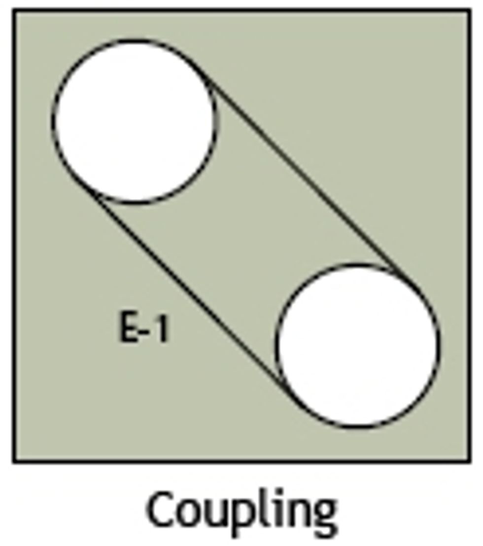 The load and process can have numerous types of faults, depending on the type of load. The most common are worn parts, broken components and bearings. Test instruments capable of detecting common load and process equipment problems include ESA, vibration, infrared and ultrasonics.