IDENTIFYING TORSIONAL FAILURES
Identification of torsion fatigue failures is straightforward. Just look for the fracture oriented 45 degrees to the shaft centerline, like the example in Figure 1. The fracture face typically has one or more origins, a fatigue zone with progression lines and an instantaneous zone.

Figure 1: Torsional fatigue fracture of a pump shaft with fracture face 45 degrees to the shaft
A large fatigue zone and small instantaneous zone mean the fatigue load was small. A small fatigue zone and large instantaneous zone mean the fatigue load was high. More information about fatigue failure characteristics can be found in the "Preventing Mechanical Failures - An Introduction to Failure Mode Identification" article in the February / March 2012 issue of Uptime.
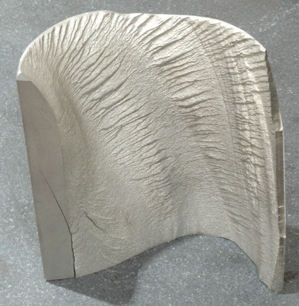
Torsional fatigue fractures frequently occur in a shaft that is inside a hub or coupling. These fractures usually start at the bottom of a keyway and progress around the shaft's circumference. In Figure 2, the fracture travels around the shaft, climbing toward the surface so the outer part of the shaft looks like it was peeled away. The fracture surface has characteristics of a fatigue fracture: one or more origins, ratchet marks and a fatigue zone with progression lines. The shaft fragment is usually held in place by the coupling or hub, so there is typically a very small or no instantaneous zone.

Figure 2: Torsional fatigue fracture of a shaft inside a hub that started at the keyway on the left-hand side and progressed around the shaft
A less common torsional fatigue failure is caused by reversing loads. When the load changes direction, two fractures occur at 45 degrees to the shaft centerline. Figure 3 shows a shaft with a reversed torsional fatigue fracture starting at the keyway.

Figure 3: Reversed torsional fatigue, where two 45 degree cracks started at the keyway
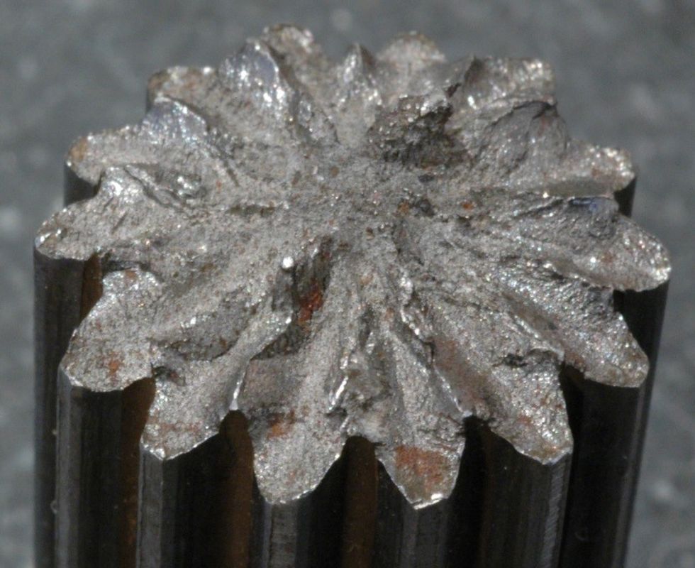
Reversed torsional fatigue fractures may have a starburst pattern. Each of the splines in Figure 4 has two cracks, each at a 45 degree angle. These usually occur on splined shafts that rotate in both directions.

Figure 4: Reversed torsional fatigue failure of a splined shaft; each spline has two cracks, each at 45 degrees to the shaftIf there are two 45 degree fracture planes in a shaft whose load does not change direction, it is an indicator of torsional vibration.
A shaft fracture may have both torsion and bending fatigue forces applied to it. When this occurs, the orientation of the fracture face may vary from 45 degrees to 90 degrees with respect to the shaft centerline. The shaft shown in Figure 5 combines dominant bending with torsion, so the fracture is closer to 90 degrees.
The fracture angle offers key evidence. If the angle of a fatigue failure is:
- Closer to 90 degrees, it is a dominant bending force.
- Midway between 45 degrees and 90 degrees, it is a combination of torsion and bending forces.
- Closer to 45 degrees, it is a dominant torsion force.

Figure 5: Fatigue failure caused by bending and fatigue that started at a keyway; the fracture angle is between 45 and 90 degrees and progression lines are visible
Evidence of torsional fatigue also may be found on gear and coupling teeth. Most equipment runs in one direction, so wear is expected on one side of a gear or coupling teeth. Wear on both sides of a gear or coupling teeth that rotate in one direction is an indication of varying torsional force. When coupling alignment is good and wear occurs uniformly on both sides of all coupling teeth, it usually indicates torsional vibration. Alignment quality can be verified from vibration spectra and phase readings. An absence of 2X running speed spectral peaks and uniform phase across the coupling occurs when the alignment is good.
TORSIONAL MEASUREMENT AND ANALYSIS
When torque applied to a machine by an electric motor is constant, a torsional fatigue failure that requires a varying torque can occur. Changes in torque may happen in one of three ways:
- Machine characteristics - Repetitive events, such as gear mesh, vane pass, cutting tools, electric motor faults, fluid pulsation, lateral and torsional interaction, or any repetitive event that momentarily changes the shaft torque.
- Reversing loads - Occur when the direction of rotation changes.
- Torsional resonance - Occurs when the frequency of an exciting torque and a polar natural frequency are the same; the response is twisting of the shaft around its longitudinal axis (further explanation can be found in chapter 38 of reference 1).
To eliminate a torsional fatigue failure, one must be able to measure the shaft torque variation and torsional vibration. Several types of wireless systems are available for measuring torque variation and torsional vibration. Two common measurement transducers are a strain gage and wireless transmitter, and a ring containing accelerometers and a wireless transmitter. Strain gage systems can be used to measure bending, applied torque and torsional vibration. However, strain gages are small and must be carefully adhered to the shaft for good results. Rings containing accelerometers are easier to attach, but may require a bushing for different shaft sizes. They measure torsional vibration, but not shaft torque, and have a higher frequency range.
The output of a strain gage torsional vibration system can be coupled to a data collector or signal analyzer capable of accepting a 0-10 volt signal. There are two components in the output signal, absolute torque and torsional vibration.
Absolute torque is measured using DC coupling at the signal analyzer or data collector. The time waveform in Figure 6 shows the absolute torque variation using DC coupling. Torque in this shaft varied from zero to just over 7,000 ft-lbs.

Figure 6: Time waveform of shaft torque from 0 to over 7,000 ft-lbs during 7 hours
The second component of the signal is torsional vibration. AC coupling allows the torsional vibration portion of the signal to be analyzed. When the output of the torsional vibration system is AC coupled, the signal analyzer or data collector can calculate a frequency spectrum.
The spectrum in Figure 7 shows torsional vibration peaks occurring at 8 Hz and 105 Hz from an AC coupled signal. The source of these spectral peaks can be determined from machine characteristics or a torsional model.

Figure 7: Spectrum of torsional vibration
Evidence of torsional fatigue failures or measurements indicating torsional natural frequencies warrant further analysis using a torsional model. A Holzer or an eigenvector/eigenvalue matrix model will calculate the undamped natural frequencies and torsional mode shapes.
The Holzer method was developed in the early 1900s and is readily adaptable to a spreadsheet. Matrix methods are more versatile, but require specialized proprietary or matrix software to solve the matrices. Both will produce good results that can be verified with AC coupled spectrum analysis.
Modeling a torsional system requires care to ensure accuracy. A consistent set of units must be used throughout the analysis, especially where several sets of vendor prints or data are used. Details and procedures for the Holzer and matrix modeling methods can be found in the references listed at the end of this article.
PREVENTING TORSIONAL FATIGUE FAILURES
Torsional fatigue failure prevention can be grouped into three categories:
1. Correct machining, assembly and installation to eliminate:
- Incorrect fit/finish of a shaft and bore.
- Small radius in a keyseat.
- Excess clearance between the key and keyseat.
- Misalignment.
These are the easiest to fix. Frequently, the effort stops here and the failures continue. However, with more investigation, torsional fatigue failures can be eliminated.
2. Identify torque characteristics of the system:
- Machine characteristics - Repetitive events, such as gear mesh, vane pass, cutting tools, electric motor faults, fluid pulsation, lateral and torsional interaction, or any repetitive event that momentarily changes the absolute torque.
- Reversing loads - Direction of rotation changes.
Torque measurements, both absolute and vibration, can be used to identify these sources of torsional vibration. Torsional failures can be stopped once machining and assembly are correct; the variations are identified; stress analysis is done to verify components have sufficient fatigue strength; and, if required, components are strengthened.
3. Identifying and correcting torsional resonance by requiring:
- Construction of a torsional model using Holzer or matrix methods.
- Validating the model with torsional measurements.
- Changing the mass or stiffness of the system to shift one or more natural frequencies, or changing the forcing frequency of a component.
Everyone in equipment reliability knows that things interact. When this happens, changes must be made in all three categories to eliminate future torsional fatigue failures.
FITS AND FINISHES
When a torsional failure occurs in a shaft inside a coupling or hub, the fit between the shaft and bore should be verified. The clearance between the side of the key and keyway is sufficient for microscopic movement if there is not enough interference fit. Even then, low levels of torsional vibration will cause movement. The shaft and bore wear and fret, causing premature repair or failure.
The shaft and bore finish also has significant influence on the ability of the shaft and hub or coupling to tolerate torsional vibration. If the finish is rough or ridged like the surface of the shaft in Figure 8, the frictional area is reduced, leaving the shaft and bore susceptible to premature wear and fretting.
 One frequent contributor to torsional fatigue failure is a small radius in the keyseat. If the radius does not meet the ANSI B17.1-1967 (R2013) standard for keys and keyseats, it should be corrected by remachining the keyseat using a cutter with the correct radius. When this is done, an oversized key is typically required, especially when the original keyseat and key had a slide or interference fit.
The ANSI standard also defines several classes of keys and keyseat fits. When torsional vibration is occurring and an ANSI Class 1 fit is used for the key and keyseat, it may help to increase the fit to a Class 2 or 3. However, more care will be required during assembly.
The interference fit between the shaft and bore should be sufficient to transmit the torsional vibration forces in a shaft using keyseats and keys. Even if dimensions and resultant fits are within a particular standard, never assume friction is sufficient to prevent micromotion between the bore and shaft.
If torsional vibration data is available, the minimum required amount of fit may be calculated using equations that can be found in most machine design books.
CASE STUDY
The input gear in a gearbox had experienced repeated torsional fatigue failures. The failures became worse when the input shaft coupling was replaced with a different type coupling. Torsional vibration measurements with a strain gauge and a Holzer analysis identified a torsional natural frequency at the motor speed. The change in angular deflection was greatest near the input gear.
Several coupling designs were evaluated using Holzer modeling to determine which one would move the natural frequency away from the motor speed and reduce the angular deflection at the input gear. A coupling was selected that shifted the natural frequency and reduced the angular deflection at the input gear. Results of the torsional mode shape at motor running speed before and after the change are shown in Figure 9. The natural frequency changed about 10 percent and the angular deflection at the input gear was reduced 60 percent. Note that both plots vary from 0 - 1 (normalized), but maximum value of angular deflection after the coupling change was reduced 80 percent.

Figure 9: Before and after results of coupling change
CONCLUSION
Torsional resonance and failures are more common than recognized. They can be eliminated by:
- Careful machining and assembly.
- Measurement and correction of torsional variations.
- Changing the natural frequency(ies) of the system.
Analysis of a torsional failure may seem daunting at first, but it is always easier and less expensive than fixing repeat failures.
References:
- Harris, Cyril M. Shock and Vibration Handbook. New York City: McGraw-Hill Companies, 1996.
- Nestorides, E.J. A Handbook on Torsional Analysis. Cambridge: Cambridge University Press, 2011.
- American Petroleum Institute. API Standard 684, Tutorial on the API Standard Paragraphs Covering Rotor Dynamics and Balancing (An Introduction to Lateral Critical and Train Torsional Analysis and Rotor Balancing). Washington, D.C.: American Petroleum Institute, 1996.
- Shigley, J., Mischke, C. Standard Handbook of Machine Design. New York City: McGraw-Hill Companies, 1996.


 One frequent contributor to torsional fatigue failure is a small radius in the keyseat. If the radius does not meet the ANSI B17.1-1967 (R2013) standard for keys and keyseats, it should be corrected by remachining the keyseat using a cutter with the correct radius. When this is done, an oversized key is typically required, especially when the original keyseat and key had a slide or interference fit.
