The oil and gas industry has become critical for sustained operations and long-term asset reliability. When it comes to condition monitoring, expensive technologies, extensive training, and years of development often come to mind, especially regarding rotating equipment. Tools, such as vibration spectrum analysis, thermal imaging, oil lubrication analysis, and motor current analysis, provide valuable snapshots in time and have been useful in practice for quite some time.
At Yara Belle Plaine, a fertilizer manufacturer in Saskatchewan, Canada, the use of digital cameras has long been a key component of condition monitoring for couplings and belt drives. This approach enables the plant to visually identify issues while equipment is in operation, allowing for the planning and execution of repairs with minimal impact on production and immediate attention to safety-related concerns. The captured photos provide insights into the condition of couplings under load and allow for a comprehensive view of the entire circumference.
This article shows how digital cameras are utilized at the plant to identify issues before they escalate. Let’s explore how a digital camera can be integrated into the condition monitoring toolbox. After all, a picture can be worth a thousand words.
Condition Monitoring Program Snapshot
The camera has become an integral part of Yara Belle Plaine’s condition monitoring program, allowing the inspection of moving objects that would otherwise require a shutdown for thorough examination.
Prior to the invention of the digital camera, a strobe light was often used to inspect moving parts. However, the strobe was bulky, required significant line of sight, and could not produce stored images. In contrast, the digital camera is compact, offers numerous settings, and has the ability to record videos.
The Yara Belle Plaine fertilizer plants are filled with rotating and moving equipment that operates continuously, 24/7. Some machine guards already had openings through which photographs of the moving parts could be taken on the other side, while others required modification. Some equipment, such as belt conveyors and screeners, are more exposed.
Photographs of machines running at speeds of up to 3600 rpm are easily captured in almost any lighting condition. The camera allows for inspections of couplings, drive belts, belt splices, cooling tower fans, and much more while the equipment is running, provided it is safe to do so or proper safety arrangements have been made.
The captured images have sufficient resolution to allow for detailed inspections from the comfort and safety of a computer. Five-second videos are often enough to capture abnormal motion or noises; when recorded at the appropriate resolution, they result in small file sizes that can be easily included in reports and work orders.
Since the condition monitoring program’s implementation, the camera images have effectively identified coupling defects, cracked drive belts, conveyor belt splice separations, cooling tower fan blade issues, and damaged motor cooling fans.
As a standard practice, baseline photographs are captured for many of the manufacturer’s critical and semi-critical machines, serving as a reference for comparison when issues arise and for trending purposes. The following plant cases illustrate how the use of a camera has been instrumental in diagnosing problems.
Case 1: Coupling Failure at the Primary Reformer ID Fan
During normal operations at the fertilizer plant, the vibration on the primary reformer ID fan increased from 5.5 mm/sec to 6.7 mm/sec. Although this rise did not reach the online alarm threshold, the change in vibration levels warranted an investigation to determine the cause. In conjunction with vibration analysis, photographs were safely taken while the fan was operational, allowing for swift identification of the damaged coupling. A controlled plant shutdown was planned and executed to conduct maintenance before a catastrophic failure of the coupling could occur. The root cause analysis (RCA) concluded that a change in alignment due to motor movement was responsible for the issue.
 Figure 1: The photograph showing the damaged coupling
Case 2: Coupling Failure at the Boiler FD Fan
Vibration readings alone were insufficient in definitively determining coupling issues, however, the accompanying photographs not only depicted a coupling with broken bolts and shims, but also revealed both the source and severity of the failure. This information facilitated proper planning and the implementation of safety precautions around the equipment until it could be taken offline for repairs.
 Figure 2: The photograph of coupling taken at running speed showing the broken bolts
 Figure 3: The damaged coupling in the maintenance shop
Case 3: Cracked Drive Belts on the Roll Crusher
With this piece of equipment, photos can be taken through the small openings of a guard. One such photo showed a cracked drive belt that posed a risk of breaking and damaging the other belts. If the remaining belts began to slip due to an insufficient number of functional belts, a broken belt could also lead to other belts detaching from the sheaves.
 Figure 4: The photograph taken through the guard opening clearly reveals a cracked drive belt
 Figure 5: Small guard through which photographs are taken
Case 4: Loose Drive Belts on the Bucket Elevator
The bucket elevator is located in a remote area, with the drive at the top. Therefore, utilizing a camera is an effective way to capture the condition of the belts without requiring additional visits. During one assessment, the photograph revealed looseness in the belt and also captured the belt identification numbers. A short video was also taken and included in the report. This assessment occurred during a busy loading season, allowing for maintenance work to be planned and executed without delays to the loading schedule.
 Figure 6: The photograph showing looseness in a bucket elevator belt
Conclusion
The digital camera has proven to be a valuable tool in Yara Belle Plaine’s reliability program. Frequently, defects in rotating equipment are identified and corrective maintenance is planned and executed before any production losses or safety concerns arise.
Taking photos while the equipment is running present several advantages, among them:
- Multiple images during operation provide a comprehensive view of the entire drive, enabling observation of most surfaces.
- Part numbers can be confirmed and certain defects may be visible only while the drives are under load.
When implementing this type of program, it is essential to take photographs only when it is safe to do so and to adhere to the safety protocols established by your organization.


 Figure 1: The photograph showing the damaged coupling
 Figure 2: The photograph of coupling taken at running speed showing the broken bolts
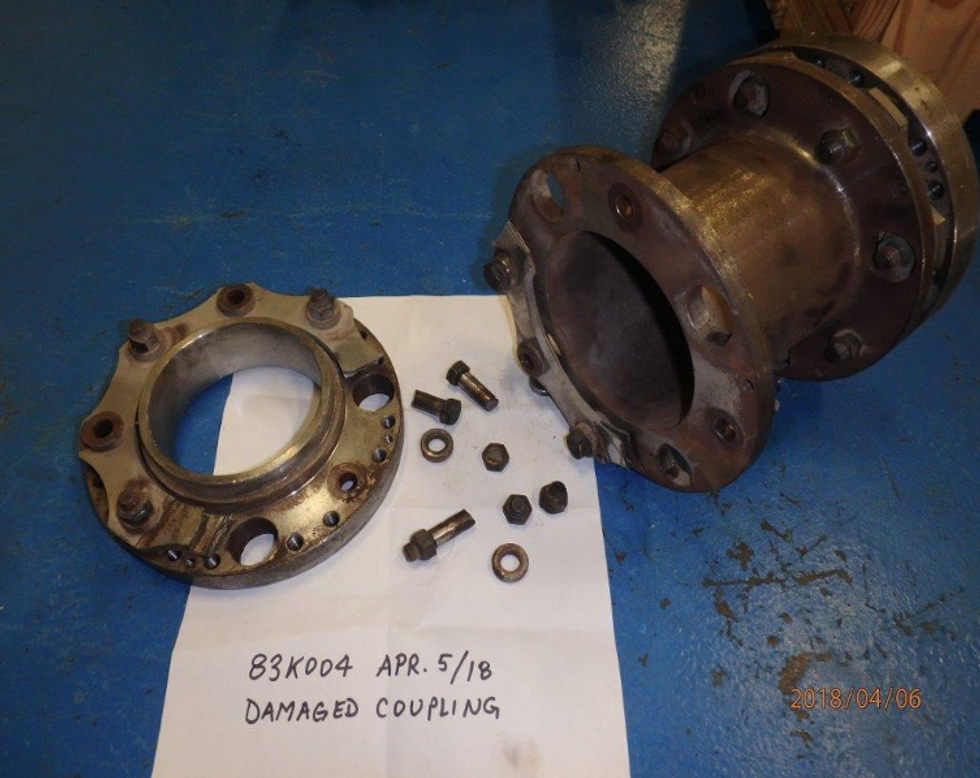 Figure 3: The damaged coupling in the maintenance shop
 Figure 4: The photograph taken through the guard opening clearly reveals a cracked drive belt
 Figure 5: Small guard through which photographs are taken
 Figure 6: The photograph showing looseness in a bucket elevator belt