- Used successfully for short rotors such as:
-overhung fans up to 2m diameter,
-pump impellers on mandrels (using a pot magnet as the swing weight).
- Also on smaller fans with two bearings that are nearer to "long" rotors.
- How used for a 10-stage pump of the ring-section design (where each impeller is assembled in turn with its matching stationary section):
-Parallel ways were clamped to the bed of a milling machine.
-Balance correction was made on the adjacent machine using an end milling cutter.
-A table was calculated and drawn up giving the depth of cut required in each case.
-Position was marked clearly on the impeller: machinist cut the required mass from the back shroud.
- Rotor must be in rolling element bearings, or set up on a mandrel and parallel ways, and not affected by crosswinds.
- For in situ balancing, take usual safety precautions so that the machine cannot be switched on while the work is in progress.
- Mark numbers around the rotor, evenly spaced. For bladed rotors, mark at the blades.
- Choose swing weight to fasten (by clamp or magnet) on rotor, to give to-and-fro oscillation time of about 20 seconds. (This gives some allowance for stopwatch reaction time).
- With the swing weight fixed to rotor at Position 1, rotate the rotor so that the weight is at one horizontal position and stationary.
- Release the weight and let the rotor swing freely under its own inertia -do not push it in any way.
- Time the to-and-fro oscillation from the horizontal position.
- Rotate the rotor so that the weight is at the horizontal position on the other side, and repeat.
- Take the average time of swing for this position
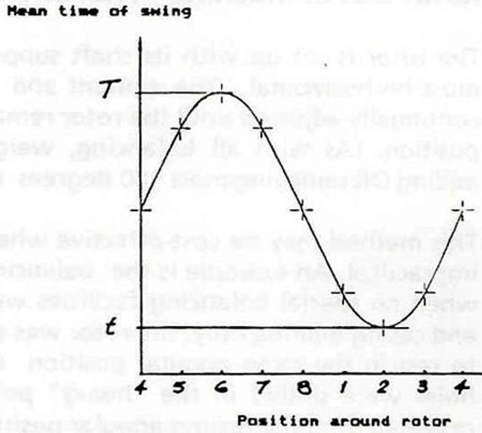
- Plot on a graph of time vs position (with position numbers evenly spaced: position 1 appears twice-at the start and the end of the position axis).

- Move swing weight to Position 2, etc. and repeat process.

- Connect the graphed points with a smooth sine wave shape graph, and read off the maximum and minimum timed of swing: T and t.
- Calculate the size of balance weight required from: - Balance weight = Swing weight ×

- Check the result if required by repeating the swing test for 3 spaced points.
- Make balance weight of the required mass, and fix it on the rotor at position of longest swing time. Allow for mass of weld.
- If the correction is to be made by removing mass from the rotor, remove it from the position of quickest swing.
Reader tip provided by, Ray Beebe, Senior Lecturer, Monash University
Thanks for the reader tip Ray. We have made a $10 donation to the Harry Chapin Food Bank per your request.
Want us to donate in your name? Click here to send in your own maintenance tip