Having wear particles provide evidence of machine problems depends on the industrial application from a clean environment to a dirty one. However, showing photographic proof and describing the surface texture, size, shape, and morphology of the particles gives us evidence that something is potentially wrong with the machine prior to major damage. This article will describe improved ferrographic instrument design utilizing the new ASTM Standard description for wear particles. Additionally, we will review the basic operating process for utilizing ferrography to pinpoint any machine condition issues.
Ferrography has been recently enhanced to lessen the subjectivity and expense of diagnosing machine problems. Using a new magnet design and standardizing the wear particle description, ferrography has taken another step forward to pointing out the machine faults.
Three of the major types of equipment used in wear particle analysis are the Direct-Reading (DR) Ferrograph, the Analytical Ferrograph (FM Ferrograph) used to make the ferrograms, and the Ferroscope used to examine the ferrograms optically. Current redesign of the magnet has significantly changed the instruments' configuration in both size and shape and most significantly in wear particle capture efficiency.
Quantitative Measurements Using the DR-6 Ferrograph
The DR Ferrograph Monitor is a trending tool that permits condition monitoring through examination of fluid samples on a scheduled periodic basis. A compact, portable instrument that is easily operated even by non-technical personnel, the DR Ferrograph quantitatively measures the concentration of ferrous wear particles in lubricating or hydraulic oil. The DR Ferrograph separates out particles having positive magnetic susceptibility by means of a high-gradient magnetic field. Magnetic separation is nearly 100% effective for ferromagnetic particles larger than 0.1 micrometers due to the new neodymium magnet design (see Figure 1), which enables us to reduce instrument size and weight and increase the wear particle deposition efficiency.

The DR Ferrograph senses wear particles at two locations. First, at the entrance deposit, usually referred to as "DL," and the second, about five millimeters downstream, usually referred to as "DS." The DR Ferrograph senses the presence of particles by measuring the amount of light attenuated at the two deposition locations. The ferromagnetic separation technique causes all ferrous debris larger than 5 micrometers to deposit a few millimeters after entering the magnetic field. Consequently, the "entrance deposit" contains all the larger particles and a representative portion of the smaller particles. No ferromagnetic particles larger than a few micrometers penetrate further than a few millimeters downstream from the entrance deposit. Particle size becomes progressively smaller along the deposition path.

Wear Particle Concentration (WPC) is the sum of DL+DS divided by sample size (volume). In most cases, the sample volume is one milliliter, so WPC is simply DL+DS. Percent Large Particles (PLP) is calculated as follows:
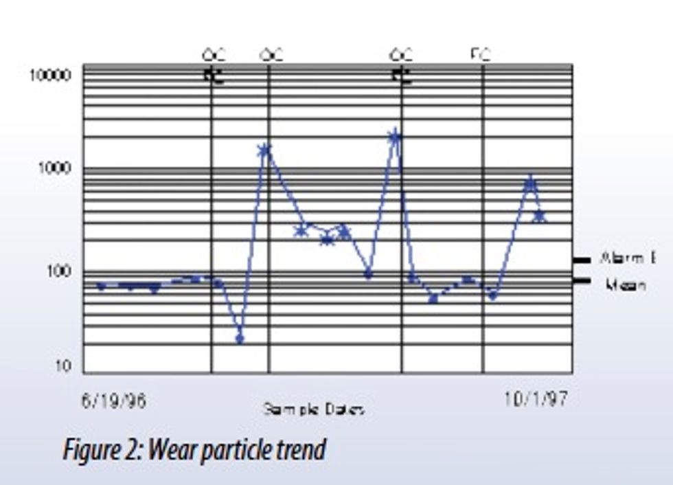
Machines starting service go through a wearing-in process, during which the quantity of large particles quickly increases and then settles to an equilibrium concentration during normal running conditions. A key aspect of ferrography is that machines wearing abnormally will produce unusually large amounts of wear particles, indicating excessive wear condition by the DR Ferrograph in WPC readings. If WPC readings are beyond the normal trend, a ferrogram sample slide is made with the fluid for examination by optical microscopy.

Figure 3: DR-6 Ferrograph
The Analytical Ferrograph FM-6 Ferrogram Maker: Additional information about a wear sample can be obtained with the FM-6 instrument, which can provide a permanent record of the sample, as well as analytical information for viewing. The FM-6 is used to prepare a ferrogram, which is a fixed slide of wear particles for microscopic examination and photographic documentation. The ferrogram is an important predictive tool, since it provides an identification of the characteristic wear pattern of specific pieces of equipment. After the particles have deposited on the ferrogram, a wash is used to flush away the oil or water-based lubricant. After the wash fluid evaporates, the wear particles remain permanently attached to the glass substrate and are ready for microscopic examination using the ferroscope.

Figure 4: FM-6 Ferrogram Maker Instrument
The Microscope: Ferrograms are typically examined under a microscope that combines the features of a biological and metallurgical microscope. Such equipment utilizes both reflected and transmitted light sources, which may be used simultaneously. Green, red, and polarized filters are also used to distinguish the size, composition, shape, and texture of both metallic and non-metallic particles. A new feature of the ferroscope is the ability to measure particles within the imagery software and provide a split-screen image to compare before and after photomicrographs once the ferrogram is heat treated.

Types of Wear Particles: Recently the ASTM organization standardized the naming description for all wear particles in ferrography, patch testing, and any other media. The standard is ASTM D7690. The wear particle descriptions are as follows:
- Rubbing Wear Particles: Normal-rubbing wear particles are generated as the result of normal sliding wear in a machine and result from exfoliation of parts of the shear mixed layer. Rubbing wear particles consist of flat platelets, generally 5 microns or smaller, although they may range up to 15 microns, depending on equipment application. There should be little or no visible texturing of the surface, and the thickness should be one micron or less.

- Abrasive Wear Particles: Abrasive wear particles are generated as a result of one surface penetrating another. There are two ways of generating this effect.
- A relatively hard component can become misaligned or fractured, resulting in a hard sharp edge penetrating a softer surface. Particles generated this way are generally coarse and large, averaging 2 to 5 microns in width and 25 microns to 100 microns in length.
- Hard abrasive particles in the lubrication system, either as contaminants such as sand or wear debris from another part of the system, may become embedded in a soft wear surface (two-body abrasion), such as a lead/tin alloy bearing. The abrasive particles protrude from the soft surface and penetrate the opposing wear surface. The maximum size of cutting wear particles generated in this way is proportional to the size of the abrasive particles in the lubricant. Very fine wire-like particles can be generated with thickness as low as .25 microns. Occasionally small particles, about 5 microns long by 25 microns thick, may be generated due to the presence of hard inclusions in one of the wearing surfaces. Abrasive wear particles are abnormal. Their presence and quantity should be carefully monitored. If the majority of abrasive wear particles in a system are a few micrometers long and a fraction of a micrometer wide, the presence of particulate contaminants should be suspected. If a system shows increased quantities of large (50 micrometers long) abrasive wear particles, a component failure is potentially imminent.
Spherical Particles: These particles are generated in the bearing cracks. If generated, their presence gives an earlier warning of impending trouble, as they are detectable before any actual spalling occurs. Rolling bearing fatigue is not the only source of spherical metallic particles. They are known to be generated also by cavitation erosion and, more importantly, by welding or grinding processes. Spheres produced in fatigue cracks may be differentiated from those produced by other mechanisms through their size distribution. Rolling fatigue generates few spheres over 5 microns in diameter, while the spheres generated by welding, grinding, and erosion are frequently over 10 microns in diameter.

Severe Sliding Wear Particles: Severe sliding wear particles are identified by parallel striations on their surfaces. They are generally larger than 15 microns, with the length-to-with thickness ratio falling between 5 and 30 microns. Severe sliding wear particles sometimes show evidence of temper colors, which may change the appearance of the particle after heat treatment.

Laminar Wear Particles: These distinct particle types have been associated with rolling bearing fatigue:
- Fatigue Spall Particles constitute actual removal from the metal surface when a pit or a crack is propagated. These particles reach a maximum size of 100 microns during the micro spalling process. Fatigue spall particles are generally are flat with a major dimensions-to-thickness ratio of 10 to 1. They have a smooth surface and a random, irregularly shaped circumference.
- Laminar Particles are very thin free metal particles with frequent occurrence of holes. They range between 20 and 50 microns in major dimension, with a thickness ratio of 30:1. These particles are formed by the passage of a wear particle through a rolling contact. Laminar particles may be generated throughout the life of a bearing, but at the onset of fatigue spalling, the quantity generated increases. An increasing quantity of laminar particles in addition to spherical wear is indicative of rolling-bearing fatigue microcracks.
Chunk Particles Two types of wear have been associated with Chunks:
- Pitch Line Fatigue Particles from a gear pitch line have much in common with rolling-element bearing fatigue particles. They generally have a smooth surface and are frequently irregularly shaped. Depending on the gear design, the particles usually have a major dimensionto-thickness ratio between 4:1 and 10:1. The chunkier particles result from tensile stresses on the gear surface causing the fatigue cracks to propagate deeper into the gear tooth prior to spalling.
- Scuffing or Scoring Particles are caused by too high a load and/or speed. The particles tend to have a rough surface and jagged circumference. Even small particles may be discerned from rubbing wear by these characteristics. Some of the large particles have striations on their surface, indicating a sliding contact. Because of the thermal nature of scuffing, quantities of oxide are usually present, and some of the particles may show evidence of partial oxidation (that is, tan or blue temper colors).
Many other particle types are also present and generally describe particle morphology or origin, such as dark metallo-oxide, red oxide, corrosive, etc. In addition to ferrous and non-ferrous, contaminant particles can also be present and may include sand and dirt, fibers, friction polymers, and contaminant spheres.
Contaminant Particles are generally considered the single most significant cause of abnormal component wear. The wear initiated by contaminants generally induces the formation of larger particles, with the formation rate being dependent on the filtration efficiency of the system. In fact, once a particle is generated and moves with the lubricant, it is technically a contaminant.
By being able to show the origin of wear in a standard manner, you can easily diagnose the machine faults and provide evidence to back up your claims via photomicrographs of the wear particles. With industry needing to operate plants reliably, techniques of this nature are a must to pinpoint where potential problems may lie. Equipment life expectancies, safety factors, performance ratings, and maintenance recommendations are predicated on normally occurring wear. However, using wear particle analysis/ferrography pinpoints the problem without taking the equipment out of service. And, as you know, we are in the world of "doing more with less." Modern integrated and automated high-speed machine systems make any interval of down time costly and non-productive. Therefore, machine designers and builders are increasingly using wear particle analysis/ferrography as realistic criteria for improvements in products such as compressors, gears, bearings and turbine components. Therefore, with the enhancements and the standardization of ferrography, diagnosing machine problems becomes easier and less expensive.

Raymond J. Dalley has been performing research, manufacturing, sales, and marketing with ferrography (wear particle analysis) for the past 28 years with Trico Corp. Currently an Instrument Business Manager, his responsibilities include being Project Manager for the Ferrographic Instrument Group. Mr. Dalley gives lectures for the Society of Automotive Engineers, National Lubricating Grease Institute, Joint Oil Analysis Program Conference, Society for Maintenance & Reliability Professionals, and the Society of Tribological Lubrication Engineers. www.tricocorp.com