The Great Bearing Paradox
L10 is a term used by bearing companies that means the number of revolutions that 90 percent of a bearing population is capable of enduring before the first signs of metal fatigue begin to be visible under a microscope on one of its rolling elements (either races or balls). This is determined by the maximum amount of load a bearing at 33 and 1/3 rpm for 1,000,000 revolutions will endure before any signs of fatigue shows up. The L10 life is a statistical projection. An L10 life of 1,000 hours means that 90 percent of a group of identical bearings, operating in identical conditions and under the same load, should last the projected L10 hours before that first sign of metal fatigue.
Bearing experts and bearing company engineers, however, tell a different story about the “real world.” They say that while this is a useful and very conservative number for design purposes, the bearing SHOULD be able to actually run 500 percent or five times that long for a useful life.
However, those in maintenance are conversely told by the SAME GROUP of bearing experts and bearing company engineers that, in the real world, these same 90 percent of bearings never even make their lower level of performance or L10, hence the “Great Bearing Paradox” that is the result of the actions by maintenance folks.
It is well known that underthe right conditions,it’s not unusual for somebearings to last 50 years,especially inside gearboxes
As maintenance educators teach their students, “Bearings never die of old age because maintenance supervisors, craftspeople, operators, lubricators, stores personnel, and others continue to invent all kinds of ingenious ways to torture them, resulting in their premature death long before they achieve their L10 life expectancy!”
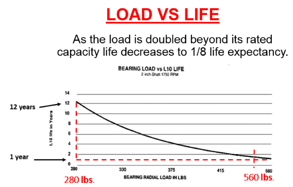
The graph in Figure 2 shows how increasing a bearing’s load shortens L10 life as radial load is increased to a point at which the bearing is compromised. Notice that if the life expectancy is 12 years at 280 pounds of load, look what happens if that load is doubled to 560 pounds. The expected life is reduced to just under two years, an exponential reduction in bearing life.
Now, let’s consider this same bearing with a speed change. If you are running it at 1,000 rpm and it has a projected similar life expectancy of 12 years, what is the impact of doubling the speed to 2,000 rpm? As you can see, the bearing life is cut in half. At 3,000 rpms, it is cut in half again, but the speed relationship doesn’t nearly degrade life expectancy to the same degree as load does.
Some would argue that the mechanism of failure is not overloading the bearing material, but a reduction in oil film thickness usually brought about by unbalance or misalignment of the machine. Obviously, oil film thickness must be compromised before any metal to metal contact and subsequent overloading of the bearing material can occur.
On the other hand, others may argue that it is the actual overloading of the bearing material itself that is the primary cause of failure. At any rate, it is clear and agreed upon that excessive loads cause premature, and too often unexpected, bearing fatigue and eventual failure.
L10: The number of revolutions that 90 percent of a bearing population is capable of enduring before the first signs of metal fatigue begin to be visible under a microscope on one of its rolling elements.
The machine designer carefully chooses bearings that should provide adequate life for the calculated speeds and loads. Your task is not only to detect impending bearing failure and carefully analyze the symptoms of failure, but to determine and act upon the root causes using a combination of all available tools.
By doing so, you will find that many additional defects and/or assembly errors are introduced along the way, which either add additional load, compromise the lubrication, or both. Assembly by construction and/or maintenance often results in unnecessary looseness; overtightened bearings; bearing housing and shaft fit and tolerances that are just flat-out wrong (e.g., too tight or too loose); wrong length keys; pipe strain; incorrect placement of components on shafts, like belt sheaves not being as close to the bearing housing as possible; wrong lubricants; components not balanced to Grade G1.0, like impellers; missing or wrong coupling bolts; and many others. All of these factors, of course, add load and increase vibration, which eventually and often dramatically shortens the bearing life and, just as often, requires a lot of excess energy to drive the machine until failure.
Real-Life Example
Here is a real-life example that illustrates how defect elimination and precision installs and rebuilds can enhance bearing life.
On a pump reliability improvement project, the company couldn’t run a high criticality pump for six weeks between scheduled outages. In no particular order, the following problems were found:
DEFECT 1: The mechanics said they achieved precision alignment specs and soft foot was also checked and eliminated. Upon a careful recheck, both were found to be untrue. Realigning and eliminating soft foot resulted in a significant reduction in overall vibration, as well as a three percent reduction in electrical power usage.
DEFECT 2: Thrust bearings were being installed incorrectly, leaving the bearings with no preload and excess axial movement. This could have easily destroyed the impeller and/or wear plate, at a minimum. Fortunately, this was found and eliminated as the rebuilt power end was double-checked before installation.
DEFECT 3: The impeller, factory balanced at G1.0, was cut to a reduced diameter for the particular service pump specs and not rebalanced.
DEFECT 4: With pumps in this area running hot, some “rocket scientist” decided to increase the viscosity of the oil from 68 to 150 and, at the same time, with bearings running 180 to 200 degrees F, add cooling water spraying on the outside of the cast iron bearing housings, thus reducing the diameter further and the bearing clearance even more.
DEFECT 5: Several original equipment manufacturer (OEM) spare shafts were checked, including the one used in the rebuild, and were found to exceed the fit and tolerance dimensions from both the pump manufacturer and the bearing manufacturer at the bearing fit surface on the shaft.
DEFECT 6: The pump running a mechanical seal was found to have a shaft 0.002 undersized where the sleeve fits the shaft and the identification of the sleeve from a third-party supplier was found to be 0.003” too large, resulting in a sleeve to shaft fit of 0.005 total looseness. And they wonder why they can’t make mechanical seals run between outages!
DEFECT 7: At 3,600 rpm on a 2-foot diameter shaft, they were using a set screw coupling rather than a shrink fit.
DEFECT 8: The same coupling was running out 0.012”. Subsequent checks revealed it bored off center in a 3 jaw chuck, which every real machinist knows is the wrong way to do it!
DEFECT 9: Using a noted pipe strain acceptance test, both the discharge piping and the suction piping (which failed, of course) were causing the cast iron rotating power end and stainless casing to distort, putting the bearing housings out of alignment with each other.
You cannot make this stuff up! These are common problems seen all the time when doing a deep dive into a failure. If it were not so criminal, it would be funny.
The Solution
If maintenance management would just realize the value of eliminating these defects AHEAD of starting and running rotating equipment, not only would uptime improve, but they would not have to spend so much time and money inspecting, doing vibration checks, infrared, oil analysis and, not to mention, the countless unnecessary replacements.
All of these are great and necessary tools, but they simply help you mitigate failure by hopefully scheduling an expensive and highly repetitive failure to avoid unscheduled downtime only.